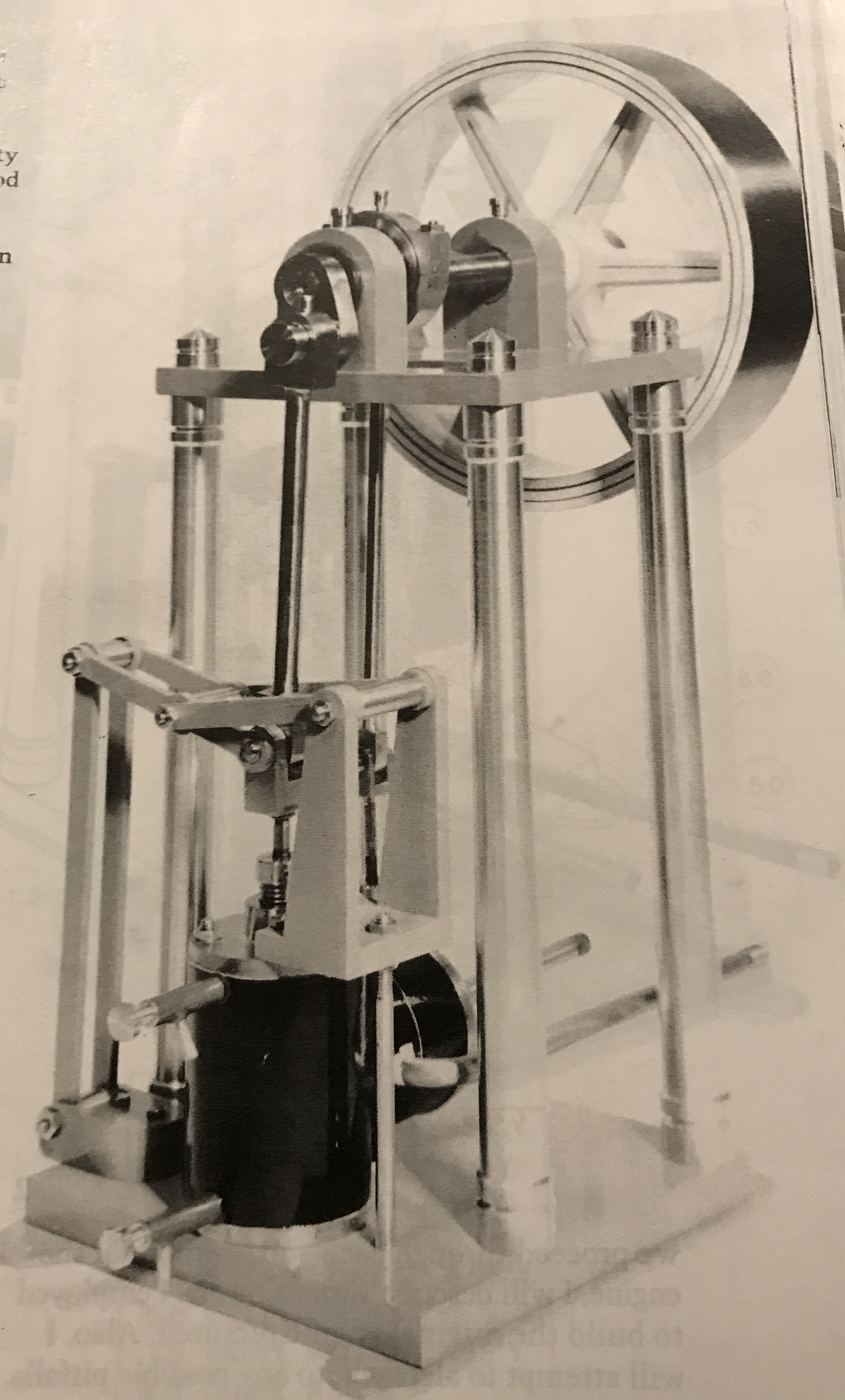
Building this engine is described in "The Shop Wisdom of Rudy Kouhoupt", pg, 129, Village Press Inc, Traverse City, MI. Consequently, this write-up will focus mostly on aspects not covered in the book and any changes made, especially for adapting the work to my machines. As Rudy describes it, this engine, sounds very interesting and fun to watch. The overcrank is a way of ensuring the piston does not get pushed sideways by the crank. There are only a few parts that look challenging and probably all can be made on Sherline equipment, except the port face. This may require the South Bend to "bore" the mating radius.
Of course it may be a while before work on this engine is initiated. The dodecahedron library and the orrery still need more work before I call them complete. I have barely begun the water droplet project!
The first order of business is assembling a list of required materials. The required materials are seen in the following table.
| Assembly | Description | Material | Number | Dimensions | Category | H/P |
|---|---|---|---|---|---|---|
| Engine Frame | Base | Aluminum | 1 | 0.312" X 3.50" X 3.50" | Bar stock | P |
| Sub base | Aluminum | 1 | 0.062" X 3.62" X 4.25" | Bar stock | P | |
| Column | Aluminum | 4 | 0.50" X 6.000" | Bar stock | P | |
| Column mounting bolts | Steel | 4 | 10-32 X 3/4" | Screws | ||
| Guide assembly screws | Steel | 5 | 2-56 | Screws | ||
| Entablature Assembly | Entablature | Aluminum | 1 | 0.25" X 2.50" X 3.50" | Bar stock | H |
| Bearing | Bronze | 2 | 0.375" X 1.00" X 1.25" | Bar stock | P | |
| Bearing screws | Steel | 4 | 4-40 X 0.63" | Screws | ||
| Bearing oil cups | Brass | 2 | 0.19" X 0.28" | Bar stock | H | |
| Cap screws | Brass | 4 | 0.38" X 0.88" | Bar stock | H | |
| Crankshaft Assembly | Crankshaft | Steel | 1 | 0.50" X 3.625" | Bar stock | H |
| Crank | Steel | 1 | 0.25" X 1.00" X 0.50" | Bar stock | H | |
| Crankpin | Steel | 1 | 0.38" X 0.652" | Bar stock | H | |
| Flywheel Assembly | Flywheel rim | Steel | 1 | 1" X 4" | "Extra strength" steel pipe | P |
| Flywheel hub | Steel | 1 | 0.75" X 1.031" | Bar stock | H | |
| Flywheel spokes | Steel | 1 | 0.25" X 4.1" X 4.1" | Bar stock | P | |
| Steamchest Assembly | Steamchest cover | Brass | 1 | 0.125" X 1.25" | Bar stock | H |
| Steam pipe | Copper | 1 | 0.188" X 2.00" | Bar stock | P | |
| Steamchest | Brass | 1 | 0.500" X 1.25" | Bar stock | H | |
| Valve stem bearing | Brass | 1 | 0.25" X 0.44" | Bar stock | H | |
| Stuffing box | Brass | 1 | 0.375" X 0.38" | Bar stock | H | |
| Gland | Brass | 1 | 0.375" X 0.38" | Bar stock | H | |
| Valve face | Stainless steel | 1 | 0.062" X 0.50" X 0.500" | Bar stock | P | |
| Valve back | Brass | 1 | 0.31" X 0.50" X 0.50" | Bar stock | P | |
| Valve nut | Brass | 1 | 0.25" X 0.50" X 0.50" | Bar stock | H | |
| Setscrew | Stainless steel | 1 | 4-40 X 0.125" | Threaded rod | H | |
| Valve stem | Stainless steel | 1 | 0.93" X 2.41" | Bar stock | P | |
| Clevis | Brass | 1 | 0.25" X 0.375" X 0.272" | Bar stock | H | |
| Pin | Steel | 1 | 0.19" X 0.41" | Bar stock | H | |
| Cylinder Assembly | Port face | Bronze | 1 | 1.25" X 0.75" | Bar stock | P |
| Port face | Bronze | 1 | 1.25" X 0.75" | Bar stock | P | |
| Cylinder | Bronze | 1 | 1.25" X 1.625" | Bar stock | P | |
| Piston rod | Stainless steel | 1 | 0.125" X 2.75" | Bar stock | P | |
| Piston | Brass | 1 | 0.75" X 0.38" | Bar stock | H | |
| Bottom cover | Brass | 1 | 1.25" X 0.19" | Bar stock | P | |
| Top cover | Brass | 1 | 1.25" X 0.44" | Bar stock | P | |
| Gland | Brass | 1 | 0.375" X 0.38" | Bar stock | H | |
| Exhaust | Copper | 1 | 3/16" X 3.50" | Tube | P | |
| Drain valve 1 | Brass | 2 | 0.19" X 0.75" | Bar stock | H | |
| Drain valve 2 | Brass | 2 | 0.09" X 0.35" | Tube | H | |
| Drain valve stem | Brass | 2 | 0.25" X 0.56" | Bar stock | H | |
| Wristpin | Steel | 1 | 0.125" X 0.615" | Bar stock | H | |
| Clevis | Steel | 1 | 0.312" X 0.66" X 0.434" | Bar stock | P | |
| Valve Motion Assembly | Eccentric | Steel | 1 | 1.00" X 0.56" | Bar stock | H |
| Eccentric | Steel | 1 | 1.00" X 0.56" | Bar stock | H | |
| Eccentric strap | Brass | 1 | 0.25" X 1.50" X 1.50" | Bar stock | H | |
| Eccentric rod | Steel | 1 | 0.12" X 3.38" | Bar stock | H | |
| Rod end | Brass | 1 | 0.37" X 0.125" | Bar stock | H | |
| Oil cup | Brass | 2 | 0.12" X 0.24" | Bar stock | H | |
| Guide Assembly | Bottom mount | Aluminum | 1 | 0.38" X 0.62" X 1.00" | Bar stock | H |
| Vibrating link | Steel | 2 | 0.32" X 3.500" | Bar stock | P | |
| Spacer bearing | Bronze | 2 | 0.25" X 0.437" | Bar stock | H | |
| Bottom pin | Steel | 1 | 0.125" X 0.86" | Bar stock | H | |
| Top pin | Steel | 1 | 0.125" X 0.82" | Bar stock | H | |
| Support | Steel | 1 | 0.12" X 2.31" | Bar stock | H | |
| Mounting plate | Aluminum | 1 | 0.188" X 0.834" X 1.062" | Bar stock | H | |
| Radius plate | Aluminum | 2 | 0.125" X 0.56" X 1.848" | Bar stock | H | |
| Radius pin | Steel | 1 | 0.125" X 1.31" | Bar stock | H | |
| Radius bearing | Bronze | 1 | 0.25" X 0.812" | Bar stock | H | |
| Radius link | Steel | 2 | 0.075" X 0.32" X 2.008" | Bar stock | P | |
| Main link | Steel | 2 | 0.075" X 0.32" X 2.195" | Bar stock | P | |
| End bearing | Bronze | 2 | 0.188" X 0.078" | Bar stock | H | |
| Center bearing | Bronze | 1 | 0.25" X 0.653" | Bar stock | H | |
| Center pin | Steel | 1 | 0.125" X 1.036" | Bar stock | H | |
| Connecting Rod Assembly | Small end | Steel | 1 | 0.188" X 0.38" X 0.563" | Bar stock | P |
| Large end | Steel | 1 | 0.25" X 0.50" X 0.625" | Bar stock | H | |
| Rod | Steel | 1 | 0.19" X 2.69" | Bar stock | H | |
| Small bearing | Bronze | 1 | 0.188" X 0.188" | Bar stock | H | |
| Large bearing | Bronze | 1 | 0.312" X 0.343" | Bar stock | H |
After a long delay I ordered the metal I could not find today, Nov 30. The metal found has been set aside. About 20 items were ordered for a little less than $190 with shipping. It has been a week and no sight of the metal. I sent a note to Speedy Metals this morning (12/6) seeking info. Hopefully it is just a slight pandemic delay.
This is a complex project, where many parts' dimensions depend closely on other parts' dimensions. These are highlighted throughout the 18 pages of text and pictures. Notes on this text delineating these dependencies are made in the next few paragraphs.
The base needs to begin with at least one square corner. This is needed to layout the holes accurately. The three sets of holes on this base need to be aligned with the matching holes in the sub-base. Two holes should be transfered and then the parts screwed together. The rest of the holes can then be match drilled. If flathead screws are going to be used for these holes then three set of holes, A, B, & C, need to be countersunk on the bottom. (Mark the bottom and top of the plate!) The four columns need to all be exactly the same length for the engine to run properly.
Similar to the base, the entablature needs to have at least one square corner for laying out the holes. These can be transfered or match drilled from the base as needed. The smaller holes should be countersunk on the bottom if flathead screws will be used to attach the bearing blocks. (Mark the top and bottom!) It is important for the bottom surfaces of the bearing blocks to be flat and square with their sides. Both blocks can be prepared at once. Drill the holes together, but don't ream them yet! Attach the bearings to the entablature and then ream them together so the holes are perfectly aligned.
The crankshaft rod could be turned between centers to guarantee concentricity of the two sections with differing diameters. The 0.438" diameter should be checked against the bearings for a good running fit. Polish the 0.438" section with wet or dry fine sandpaper for a smooth running surface. The crank should be laid out and the holes punched, so they can be easily located in the lathe.
Take care when holding the pipe in the lathe. A faceplate is preferred. Chucks might warp the tube, which will spring back to shape upon removal leaving an out of round hole. When making the hub the hole should not be reamed and the thrust surface not turned until it is mounted in the flywheel. This ensures concentricity with the rim. Center punch the center of the spokes so this center can be 'found' later in the lathe. Purchase some stainless steel solder and heat the parts to 450°. Then the solder can be applied using a torch as needed. This will minimize warpage. Allow the flywheel to cool slowly to room temperature. Note the keyed assembly with the crankshaft.
The steam chest cover serves as a template for the chest and for the cylinder, so it needs to be carefully laid out and drilled. Index the chest to ensure correct layout of the rectangular opening and the four holes. Before soldering the valve stem bearing and the stuffing box to the steam chest align them with a #42 drill. The head of the gland can be knurled or the gland can be made from hex stock. Either will provide all of the tightening ability needed. Silver solder the valve face and back together prior to cutting the grooves on the back. Cut the clevis to length after silver soldering it to the valve stem.
Machining the saddle shape of the face of the port face is probably most easily accomplished with a boring bar or fly cutter. In any case remove material in very small increments. The bulk of the material may should be removed first by sawing. Silver solder the rough port face and cylinder prior to any further work on either part. A between centers boring bar, very sharp with a small radius, should leave a smooth enough surface so no reaming or lapping is needed. Make the covers before drilling and tapping the ends of the cylinder, so the covers can be used as template. The piston and piston rod need to be made together so they are concentric. Make a close fitting grooved mandrel to bend the exhaust copper tubing.
When facing the eccentric leave a pip. This can be used to measure the offset for the reamed hole. Mount the eccentric on a mandrel via the reamed hole to turn the screw hub. When marking out the eccentric strap, mark the edges for their holes at the same time. Also leave a gap for the saw kerf from cutting the two pieces apart. Drill the two holes on the edges first, so the two halves are aligned when screwed together via these holes. Take care when centering the bolted top and bottom straps for drilling and boring. Bore to fit the previously made eccentric.
The key to a successful guide assembly is accurate spacing of the holes. When laying them out care needs to be taken. When drilling it is important to ensure the drill does not wander. Some links should be drilled together with a temporary bushing in the first hole. Be sure to accurately size the bearings for a press fit in their matching links. Some fits need to be 'light' press fits so they can be disassembled when necessary.
When making the connecting rod, the length needs to be very accurately set. It is silver soldered to the two ends and cannot be adjusted. After pressing the bearings into the ends a reamer should be run back through the holes. Sometimes the holes will change due to pressing into place.
Make sure the assembled engine moves smoothly without binding prior to the final assembly. Before the final assembly complete painting and polishing the parts as desired. The valves need to be set. This is done by rotating the flywheel, so rotate the flywheel in the direction you want the engine to run!
The plan is to begin labelling metal with this purchase. I need to be able to tell the difference between stainless and regular steel. Also between bronze and brass. I have some 10L13/14, but no longer know which cutoffs are which.
With the metal in hand started the project in earnest December 15, 2020. I already had a 3 7/8 X 3 7/8" block of 3/8" aluminum. It doesn't come in the needed 5/16" thickness. This piece of scrap was trimmed to 3.5" X 3.5" with the band saw. There was one straight edge from the manufacturer. This edge was placed on the milling table and the piece held vertically by clamping it to the angle plate with two machinist's clamps. Using the two flute cutter the opposite edge was cleaned up and made parallel. Using a vertical parallel the other two edges were also cleaned up and made perpendicular to each other.
In order to reduce the thickness and clean up the two faces of the aluminum it needs to be fly cut. I have not been able to figure out how to hold the aluminum in the mill to accomplish this task. So I will need to use the South Bend lathe. Maybe tomorrow, when it is snowing, will be a good time to work in the unheated garage?
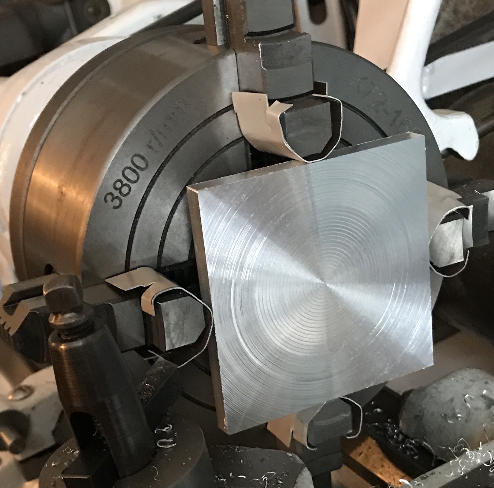
Facing the base went well. Decided not to face the back side to avoid creating two non-parallel faces. The aluminum was held in the four jaw chuck with aluminum soft jaws. It was clamped in place with parallels and tapped with a ball peen hammer to be sure it was tight against the parallels. The parallels were removed. The HSS insert was used to face the aluminum. The compound was set at about 30° and advanced 0.010" (~ 0.005" actual) per pass. The last pass was only 0.003" actual. This gave a decent finish. The final thickness as measured with a micrometer is 0.310".
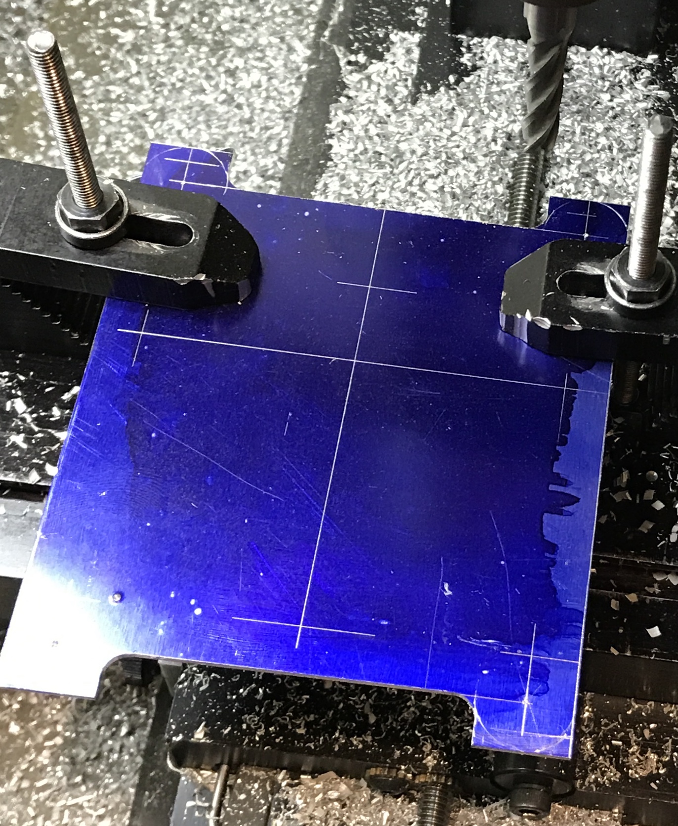
The back of the base and the one unfinished edge were sanded with 320 grit paper. The back of the base was painted with Dykem and the hole locations were marked all relative to one corner that was punch marked. This was done by first setting the height gauge to 1.250", setting the part on a 1-2-3 block and holding it vertical with a second 1-2-3 block. The height gauge made a scratch. This was repeated on the adjacent side. The height gauge was then advanced to 1.625" and again a mark was made from the left side, while sitting on a 1-2-3 block. The rest of the scratch marks were made from the granite plate at heights of 1.750", 2.250", 2.688", 2.875", and 3.25". First, light punch marks were made at each hole location and at the center of the circle. Second, heavier punch marks were made at each of these locations, except for the circle center.
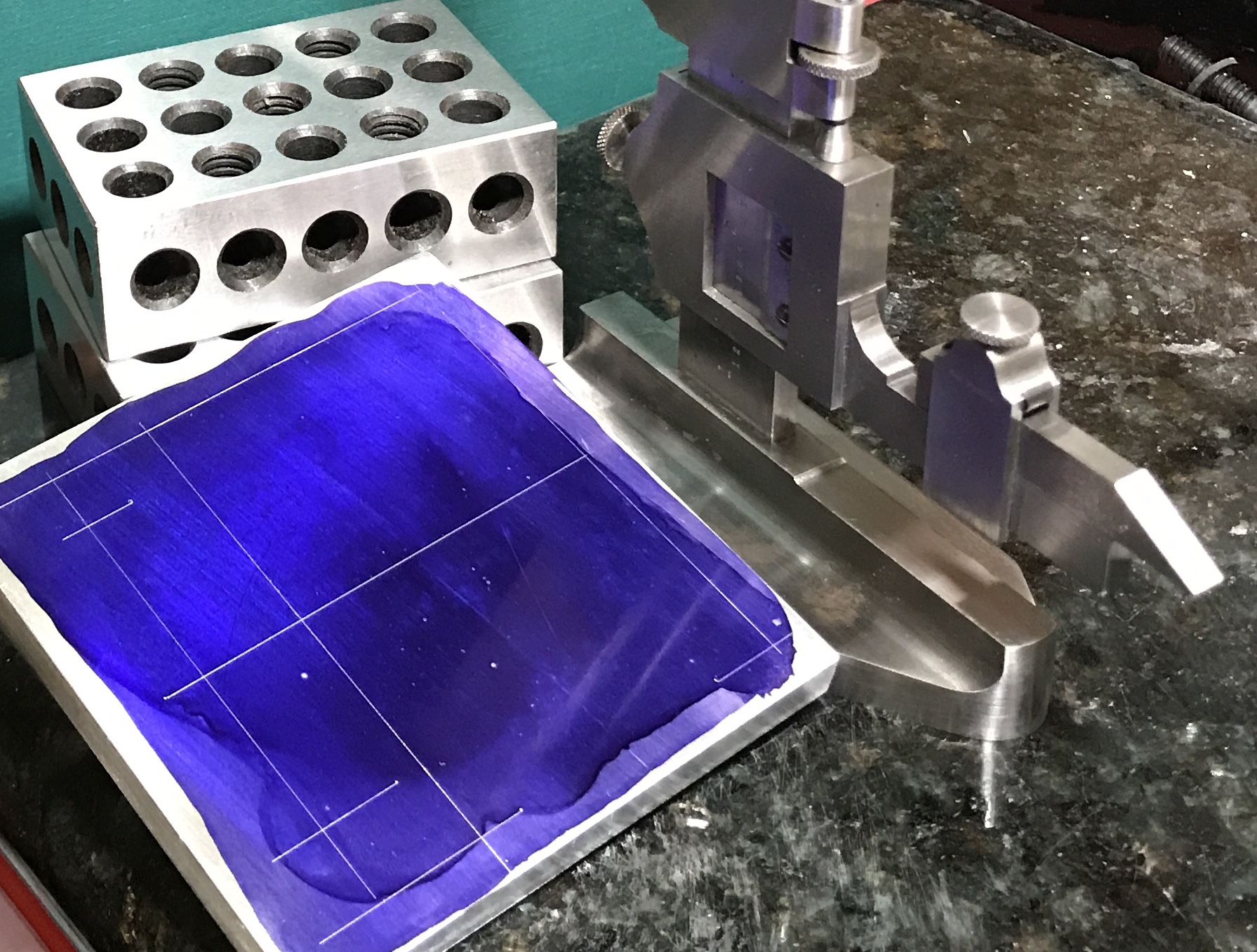
I learned how to use the height gauge finally. The marking point is placed on top of the horizontal bar with the point down. This aligns it with the 0 on the vernier scale. The scale is roughly adjusted to the desired distance. The top screw is tightened and the adjustment nut is turned to align the appropriate line on the vernier scale with the next lowest height on the main scale. For instance, since 2.688 - 2.675 = 0.013, the vernier 13 line is aligned with the 2.675 line on the main scale.
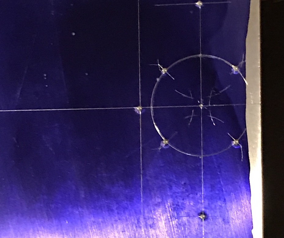
The hole circle was laid out next. The only way I know to do this is by the geometry technique of bisecting an angle. The dividers were set at 0.500" and the 0.500" radius circle was drawn. The dividers were set to about 0.4". At each of the intersections of the four center lines and the circle the divider was used to scribe arcs both inside and outside the circle. Lines were drawn through the arc intersections. The points where these lines crossed the circle were punched lightly and then punched again with the spring punch.
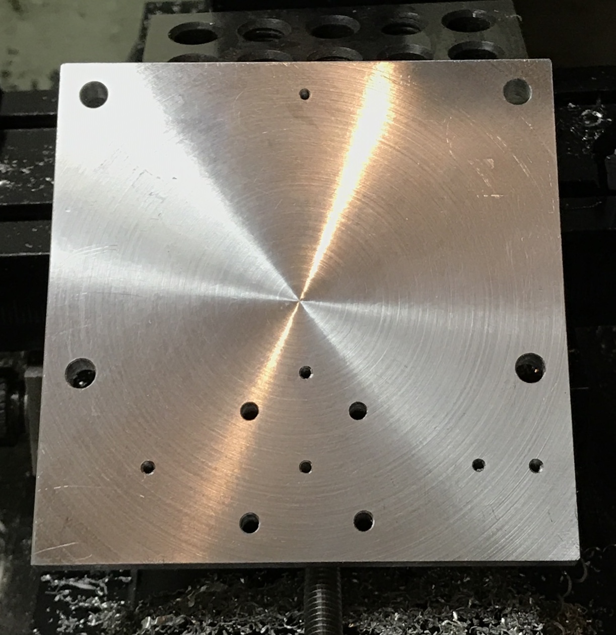
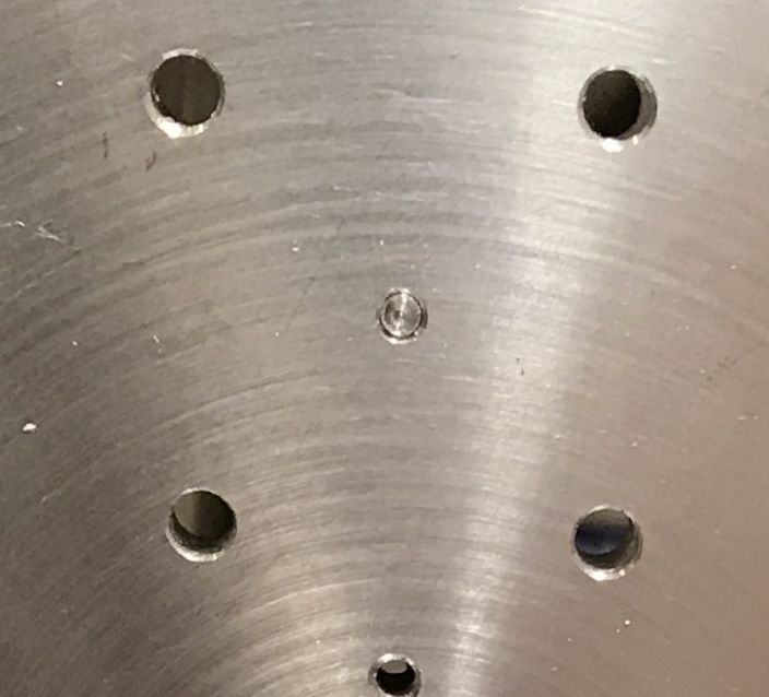
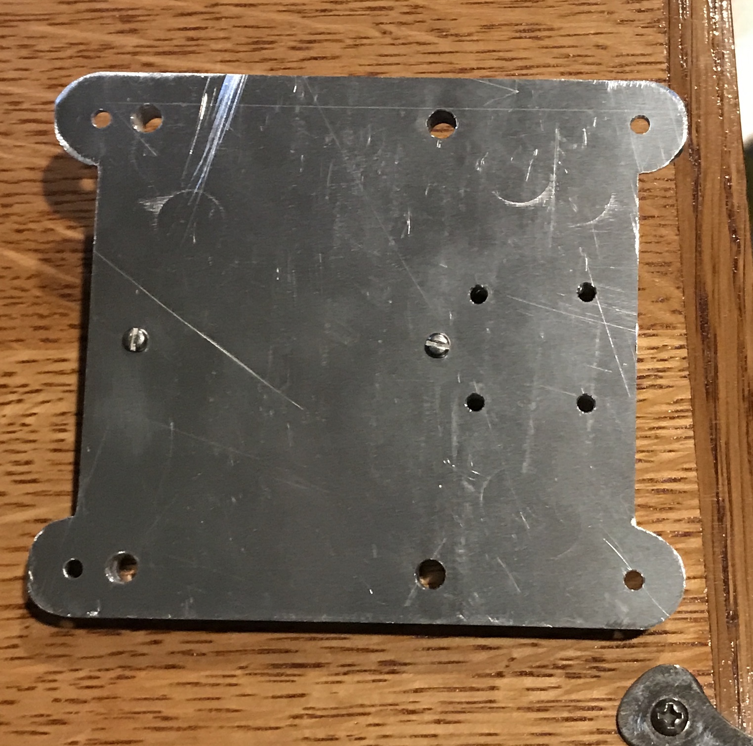
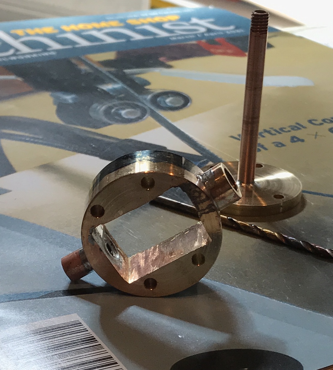
The block of aluminum was clamped on top of a 1-2-3 block on the mill with two strap clamps. The four A holes (for 10-32 mounting screws) were drilled first with a small center drill and then with a #11 drill as through holes. Then the four C holes (on the circle) were drilled with a #33 drill as through holes for 4-40 screws. Finally, the five B holes were center drilled, drilled with a #50 drill and tapped 2-56. The completed base is shown below with its one extra (!!!) hole. This will need to be plugged as this part of the base serves as closure for the bottom of the cylinder.
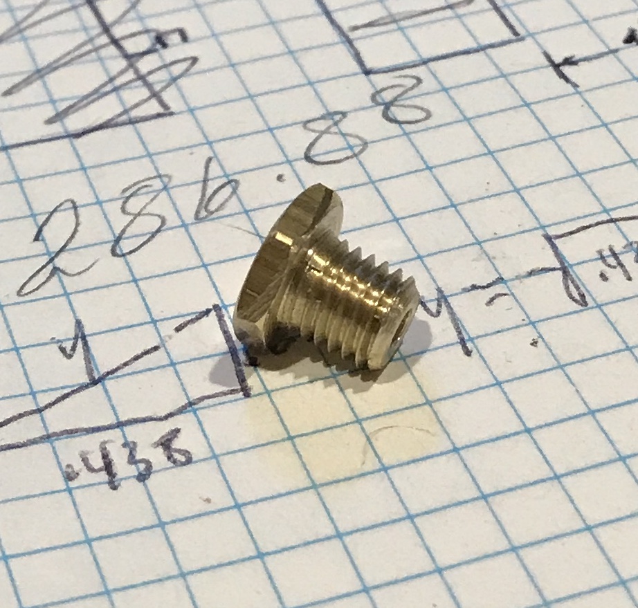
A small scrap of 1/4" aluminum rod was held in a collet in the lathe. About 3/8" was reduced in increments of 0.010". At about a diameter of 0.090" the thin shaft bent. A second scrap was reduced similarly to about 0.090" and then the cut depth was reduced to 0.005". The last two cuts of 0.003" brought it to 0.070". It was a smooth sliding fit in the hole. It was removed from the scrap with a file and bending. Since it was not a press fit a drop of Loctite was put on the shaft and it was inserted into the hole from the back.
The sub-base was the next part to make. Its overall size is 3.62" X 4.25". It provides the attachment points to any sort of wooden base. The square foot of aluminum stock was clamped to the table saw and cut with the hack saw to slightly oversize. One corner was designated for all measurements. The sub-base was painted with Dykem and the height gauge was used along with 1-2-3 blocks for marking out the holes and edges. When marking out was complete the aluminum plate was clamped to the top of a 1-2-3 block on the milling table. The two rough cut edges were cut to size and then the space between the half-round protrusions was milled to the line.
The four D holes and the two B holes were punched and then drilled in the sub-base. The sub-base plate was screwed to the base with two 2-56 screws through the two B holes in the sub-base. The two plates were then held on a block of wood by strap clamps in the mill. The four A holes were located with a #11 drill and transfer drilled through the sub-base. The sub-base was completed by transfer drilling the four holes on a circle with a #33 drill.
Four 6" lengths of 0.50" aluminum were cut from a 36" length of 0.50" aluminum rod. These were faced and center drilled on one end using a steady rest. The rods were flipped and the other end faced and center drilled. A small drill was used as a stop in the chuck and the carriage stop was used to set the overall length. Two rods were finished to 6.00" and two to 5.980"!!. The two longer rods were shortened to match the other two. I do not" know if this 0.020" will impact later operations. If it does, then I will need to make 0.020" washers to accurately space the base and entablature.
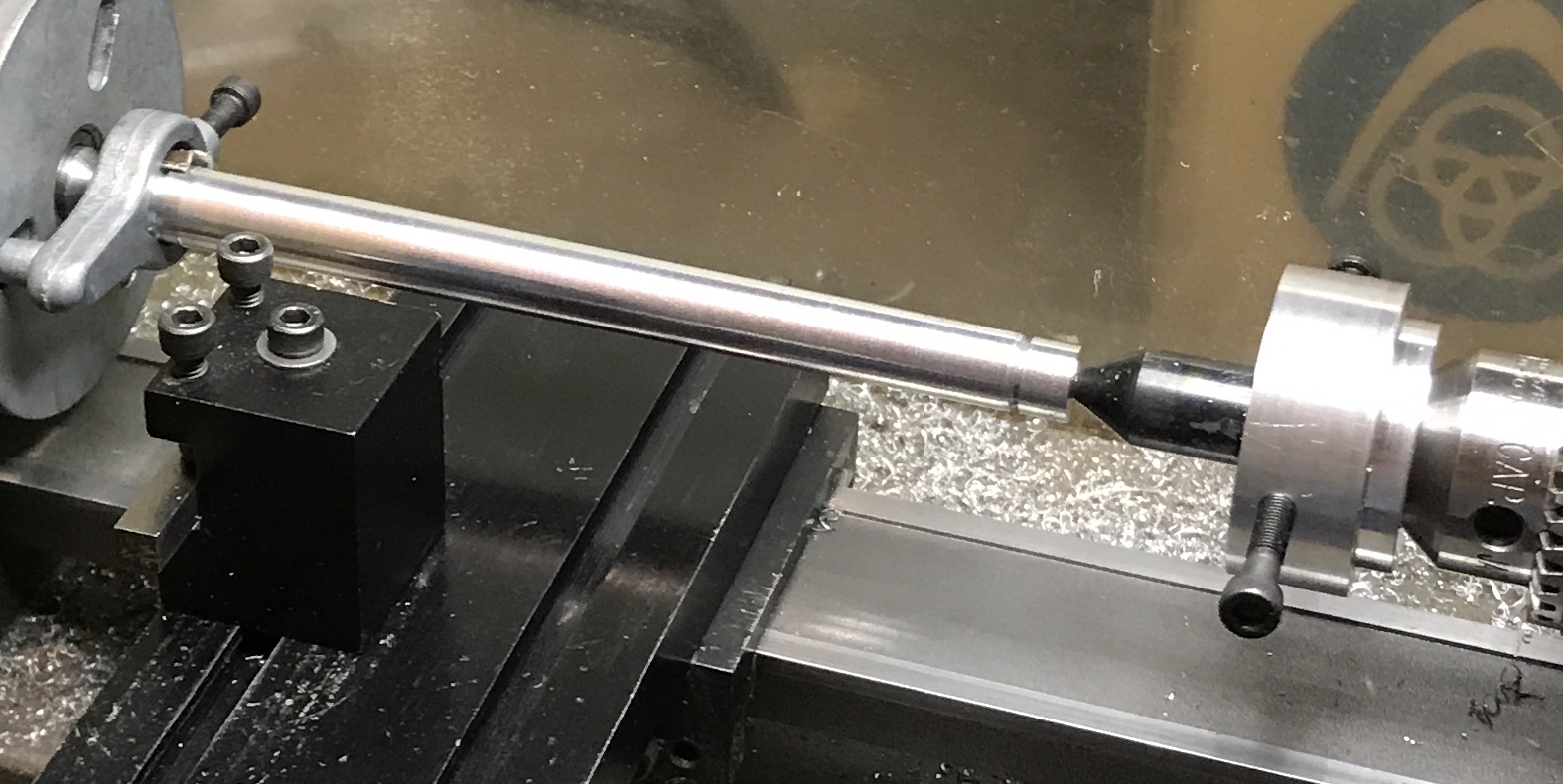
The ends of the columns were turned between centers. One end was turned down to 0.440" for 0.375". A 1/16" deep groove was made a 0.300" with a threading tool. A similar groove was made at the other end. The taper had to be cut next while turning between centers. That meant a tailstock offset was needed to cut the taper. A suitable means of "offsetting" the tailstock was devised.
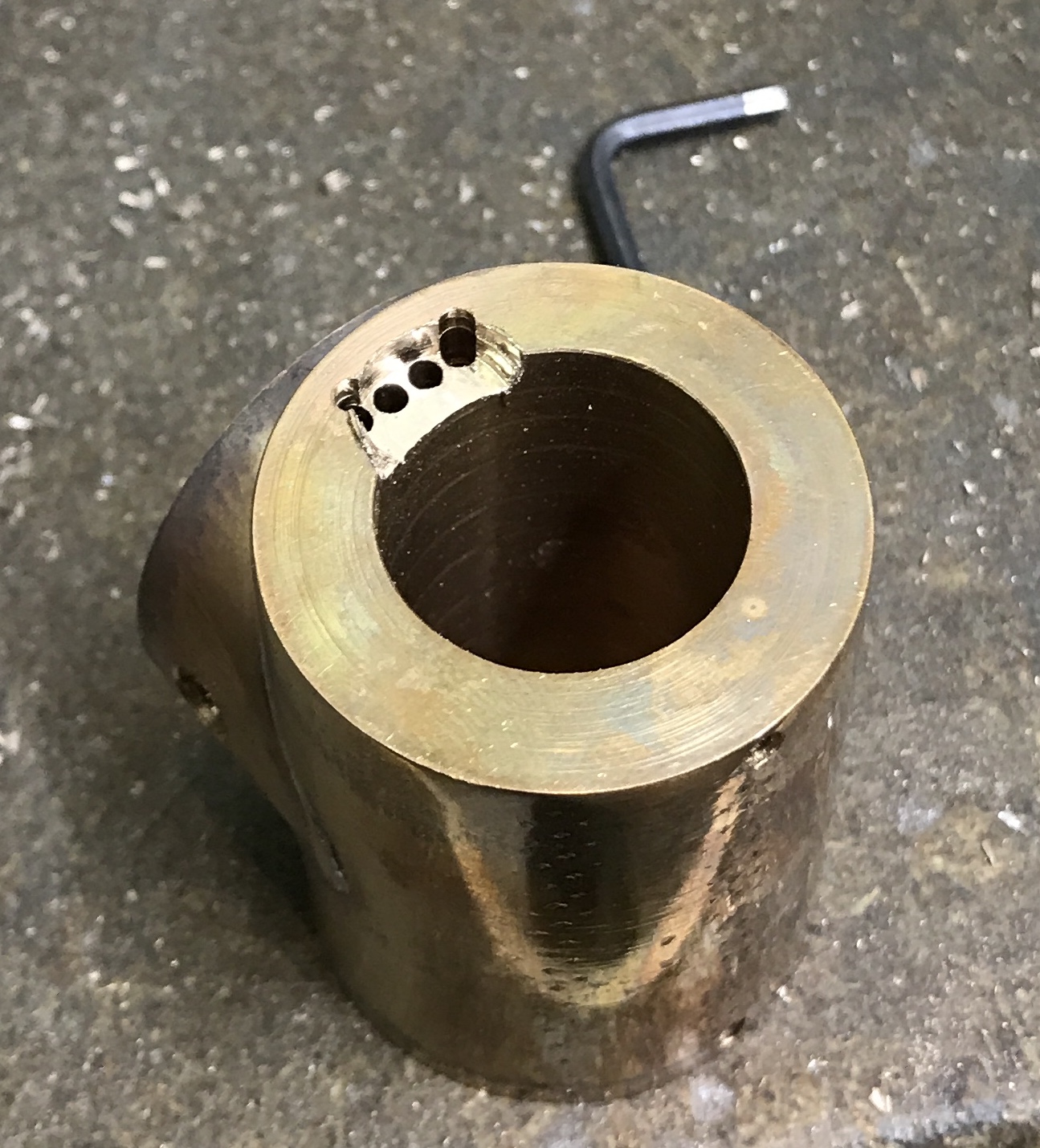
A 1 3/4" diameter rod of aluminum was cut to yield a 1 3/8" length on the bandsaw. (Still does not cut straight!) One end was faced and then the opposite end was faced. 3/4" was reduced to 1 3/8". 1/2" of this was further reduced to 3/8". This piece was chucked in the mill vise and one side of the large diameter had 0.10" removed to produce a flat. A 1/4" wide slot was cut into the large face after drilling a 1/4" hole in the center. The slot ran perpendicular to the flat side. The slot was centered and 1" long. A hole was drilled into the flat side extending into the end of the slot. It was tapped 10-32. A similar hole was drilled and tapped into the opposite end of the slot. Two "shoes" were made to help the screws hold a 1/4" shaft in the slot. A scrap of brass was cut to 1/2" X 1/4" X 1/2". 3/16" holes were milled in opposite 1/4" X 1/2" faces 1/32" deep to house the ends of the screws. This brass was held in the vise between two 1/4" scraps of wood. A center drill was centered over a different 1/4" X 1/2" face. The brass was center drilled, and drilled successively with 1/8", 3/16" and 1/4" drills. The two halves were still barely attached and were separated with a bit of hacksawing. After cleanup the shoes were fit into the slot. They were a bit too long and the screws did not seat. So about 1/32" was removed from one end of each with an end mill. The completed tailstock offset with a tailstock center installed is shown below.
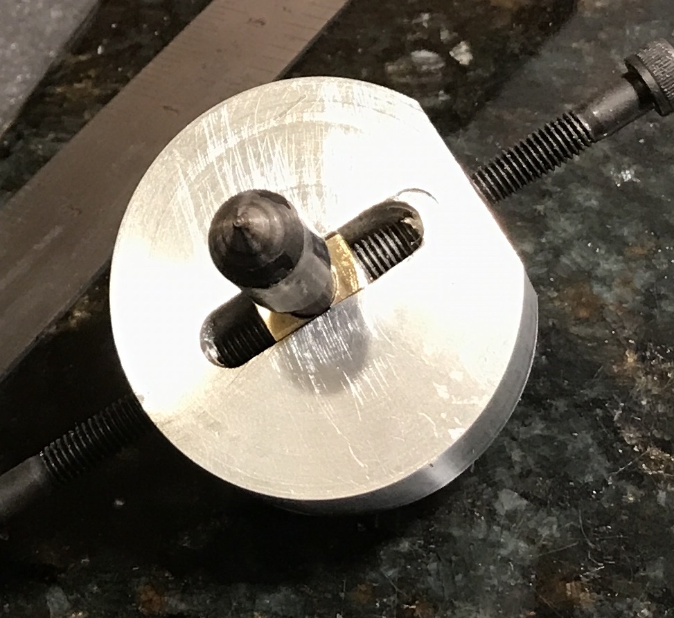
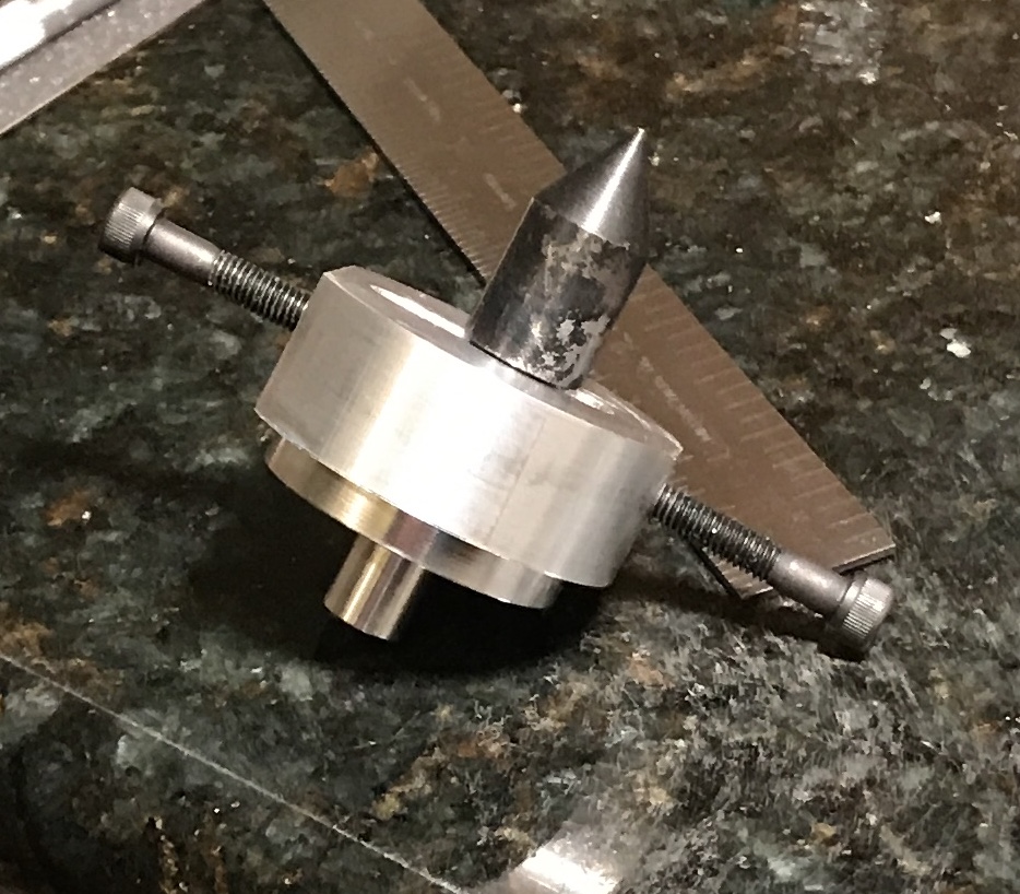
In practice the offset worked ok for a while. It was reasonably easy to adjust it to give the required 1/32" of offset. I was able to taper a column, but near the end a large vibration crept in and the tapering had to stop. The tailstock center used in the offset has a 1" shaft. This is too long and not sufficiently rigid. A tailstock center with a 1/2" long shaft will be made to see if this will eliminate the vibration. A 1 1/2" length of 9/16" drill rod was cut and faced. The faced end was reduced to 0.25" for a length of 7/16" to fit completely within the groove. This end was held in a collet and the headstock was offset to 30°. The end was cut to almost a point. The tailstock center was heated to cherry red and quenched in oil.
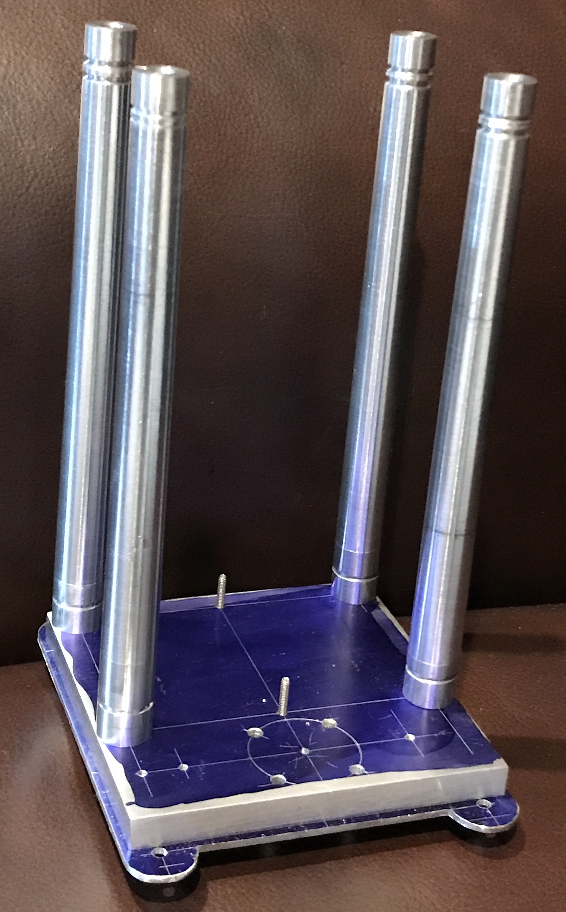
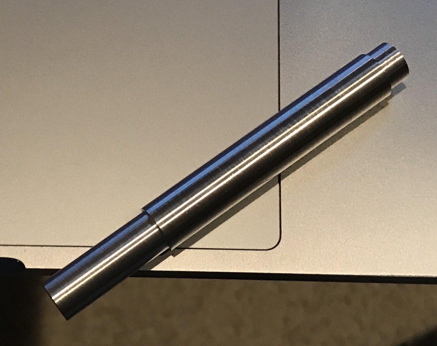
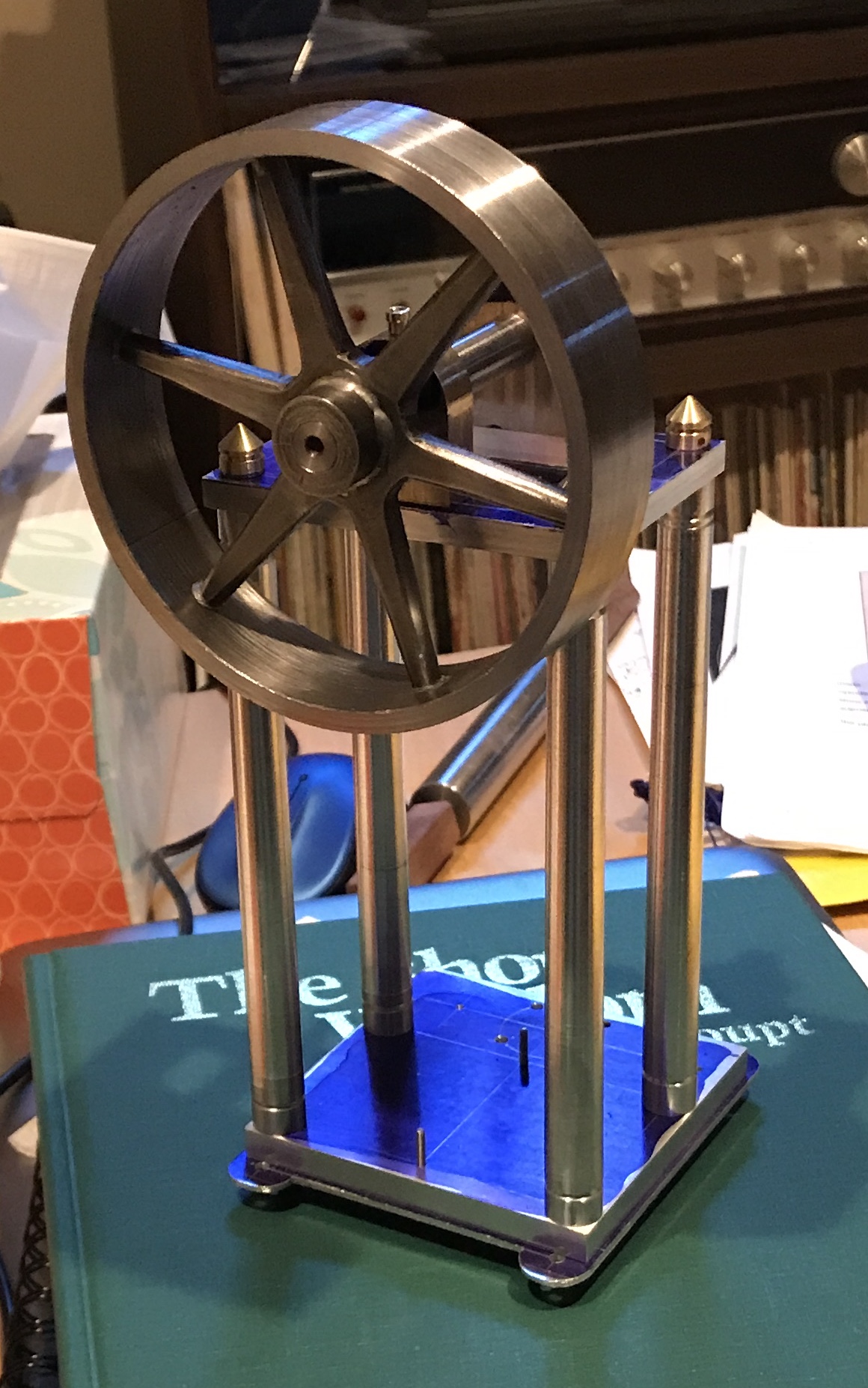
The new tailstock center worked like a champ. There was minimal vibration and the next three columns were tapered easily. A second groove was cut in the top end of the next three columns. The threading tool was aligned with the lower side of the groove and moved lower by 0.10". The groove was cut about 0.05" deep. Some sanding was done but will need to be redone. Drilling and tapping the ends was more difficult than expected. It was very difficult to hold the column end tight enough in soft jaws while using the steady rest. This might be due to poor alignment between the steady and chuck centers. In any event the ends were drilled 3/8" deep and threaded 10-32. The first column probably needs to be remade. For some reason the hole in the small end is not centered!?! This column was remade and all were cleaned up as needed between centers. The second picture below shows the parts made to date assembled. Not sure what screws to use so no screws have been cut to fit yet.
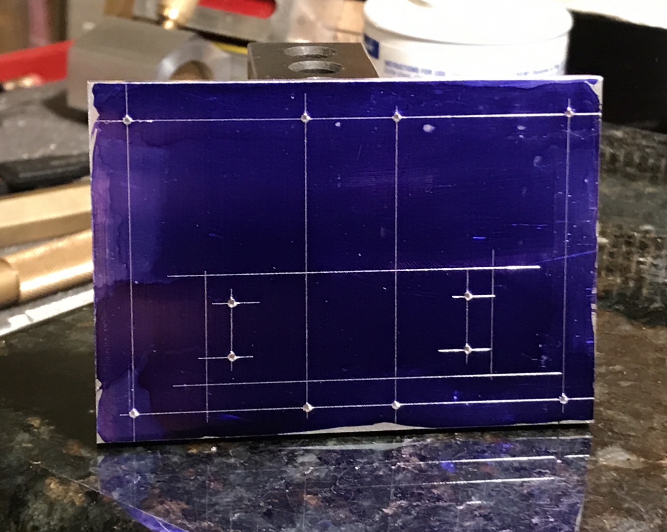
The entablature was started next. A 1/4" X 2.5" X 3.5"rectangle of aluminum was cut from a blank with a hacksaw. Similar to the base it was squared up on the four edges. One corner was marked as the reference. All layout was done relative to this corner. The layout was done similarly to the base and sub-base with the vertical height gauge and two 1-2-3 blocks. The holes were first punched with a prick punch and then an automatic punch. The picture below shows the layout prior to drilling/machining.
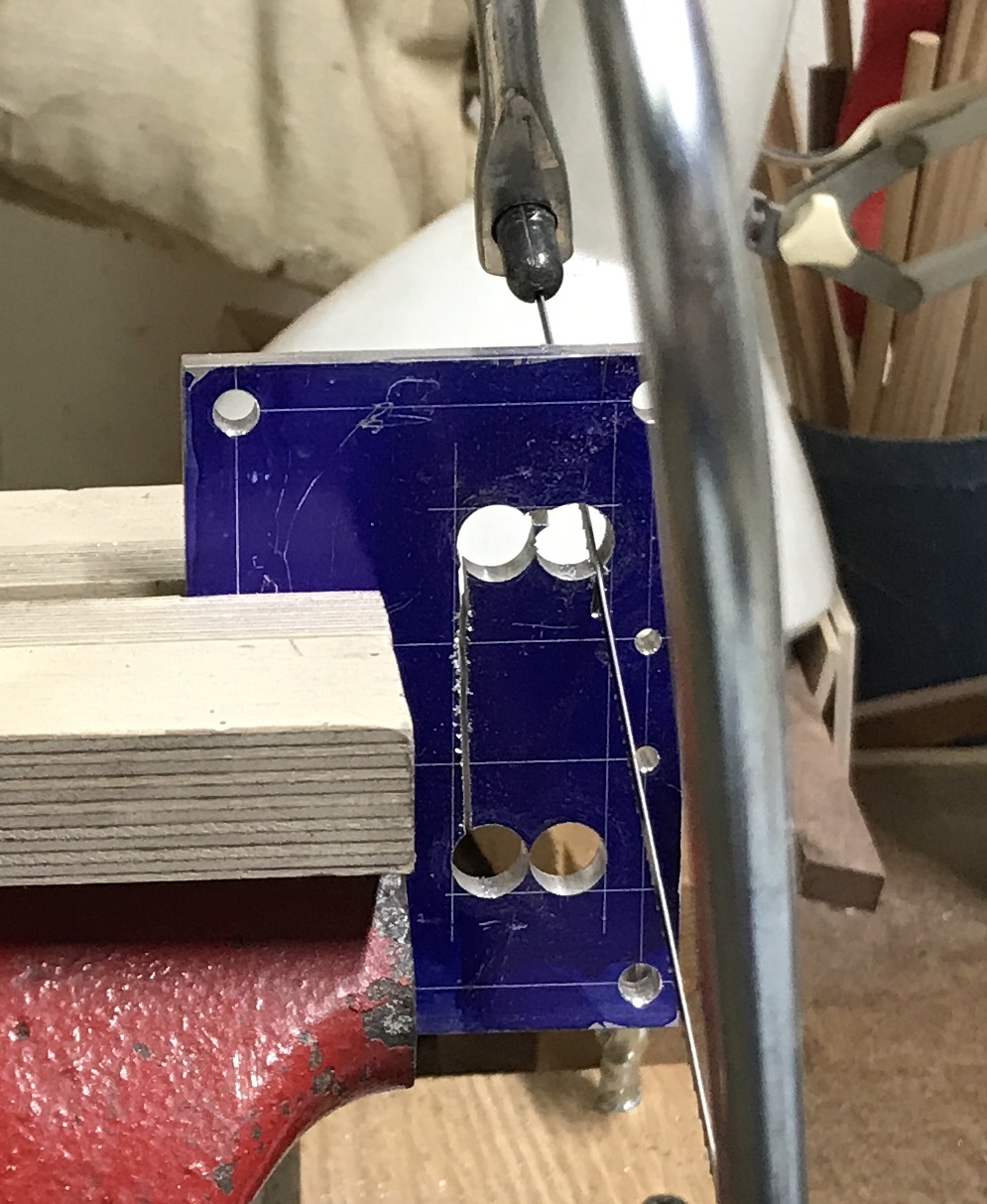
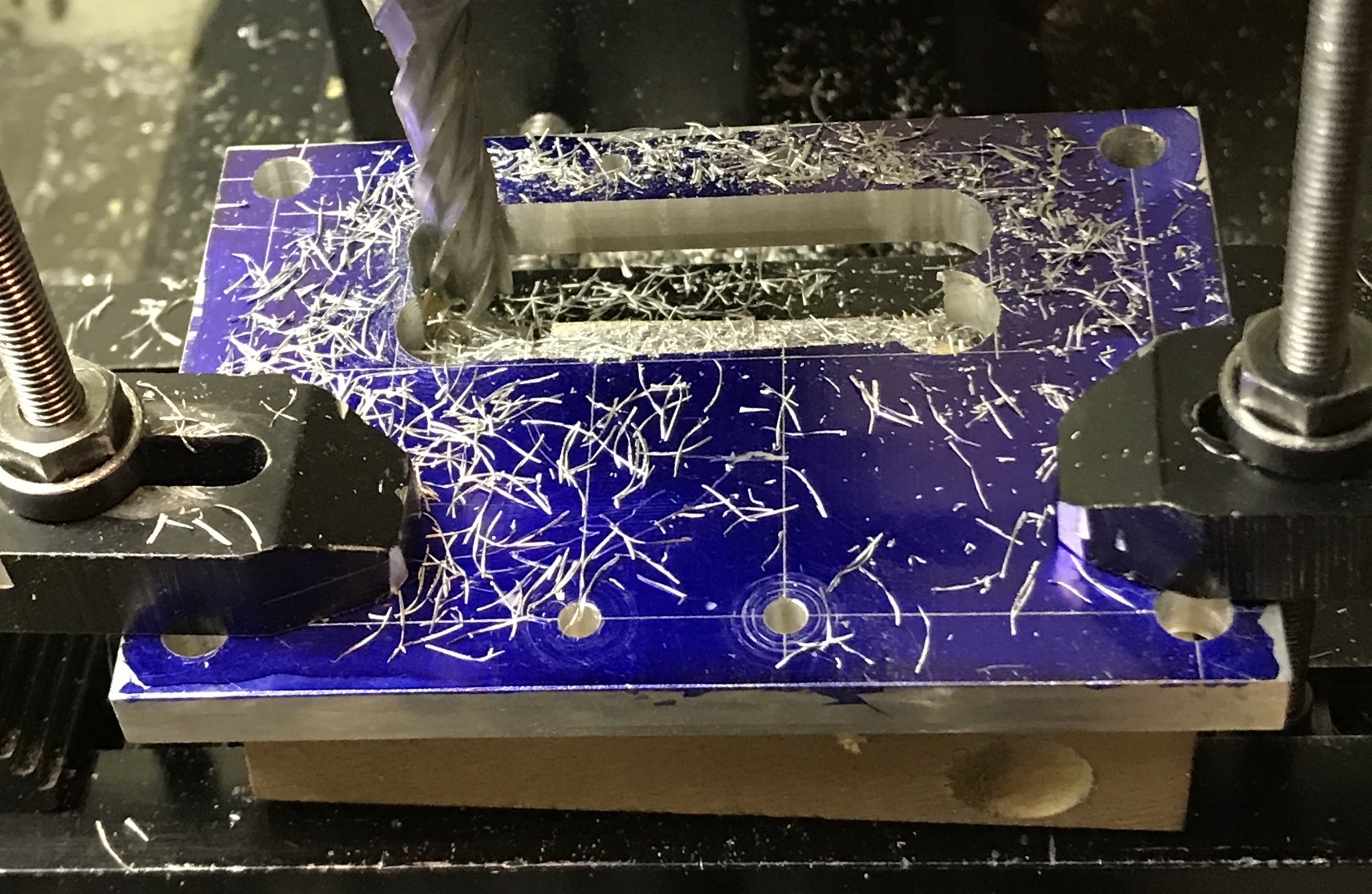
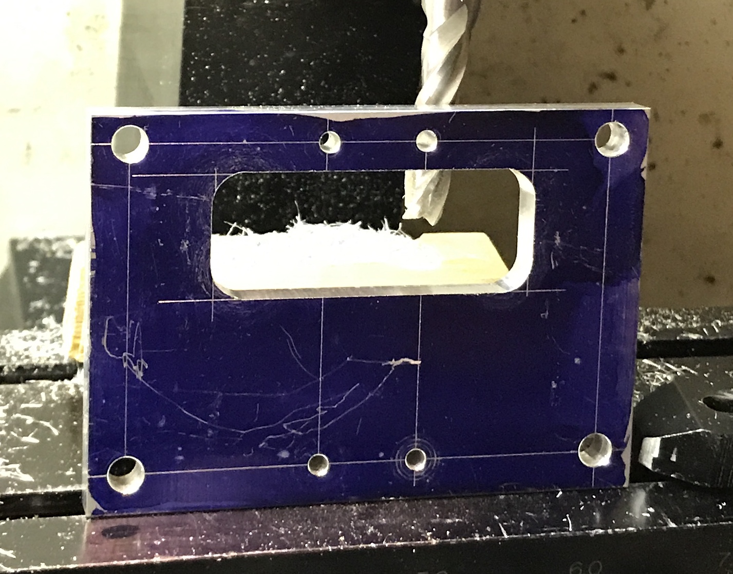
The twelve holes were drilled. The four holes for the column screws were drilled first with a center drill and then through with a #11 drill. The four bearing mounting holes were drilled starting with a small center drill and then drilled through with a #33 drill. Finally, the four holes that define the cutout were drilled first with a center drill, followed by a 3/16", 1/4", 5/16", and 3/8" drills. The bulk of the slot was removed with a coping saw. The sawing went reasonably quickly once I realized that the saw cuts on the pull stroke and should be pulled at a downward angle. To complete the part the slot was cleaned up with an end mill. The next three photos document this process.
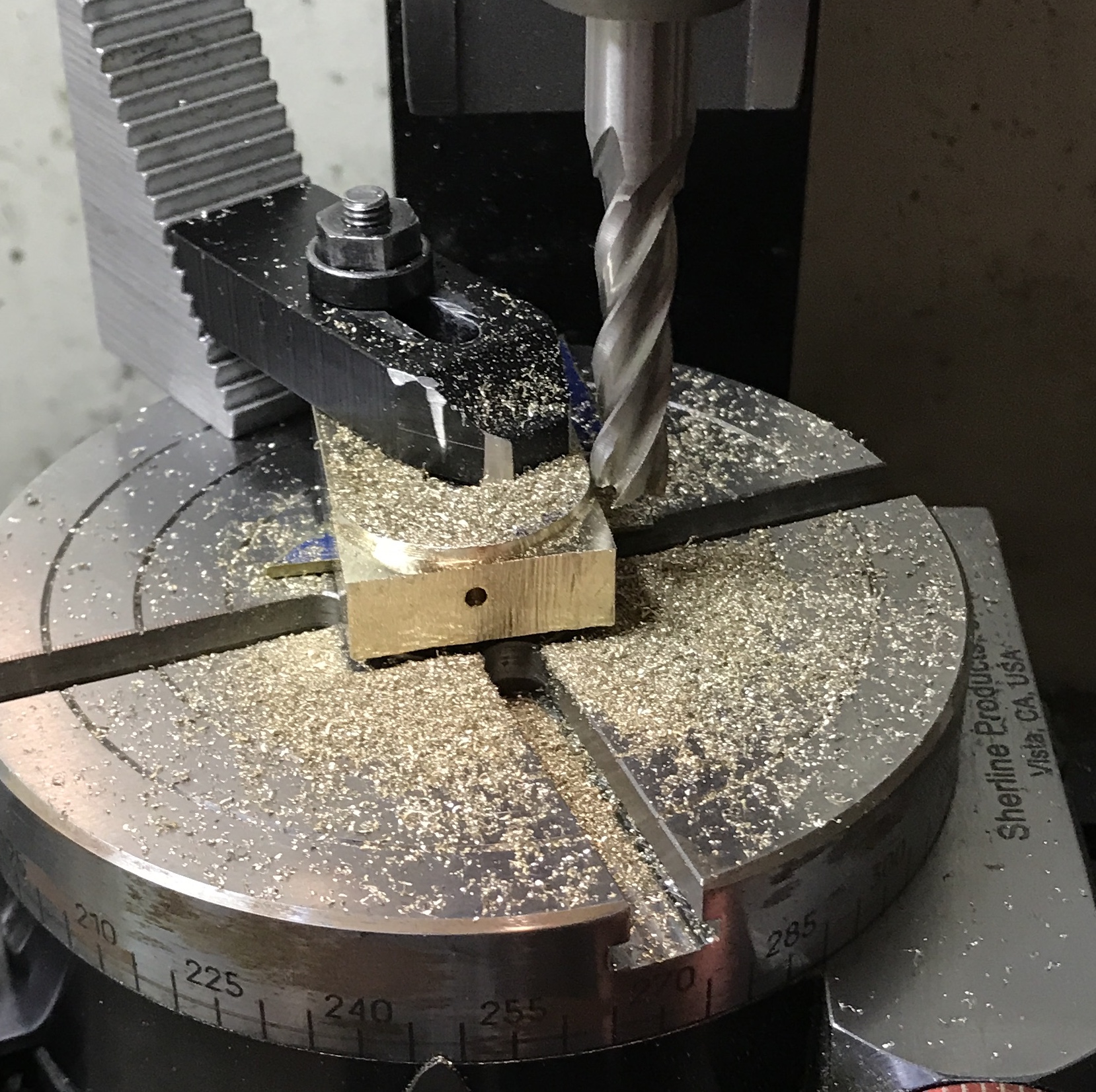
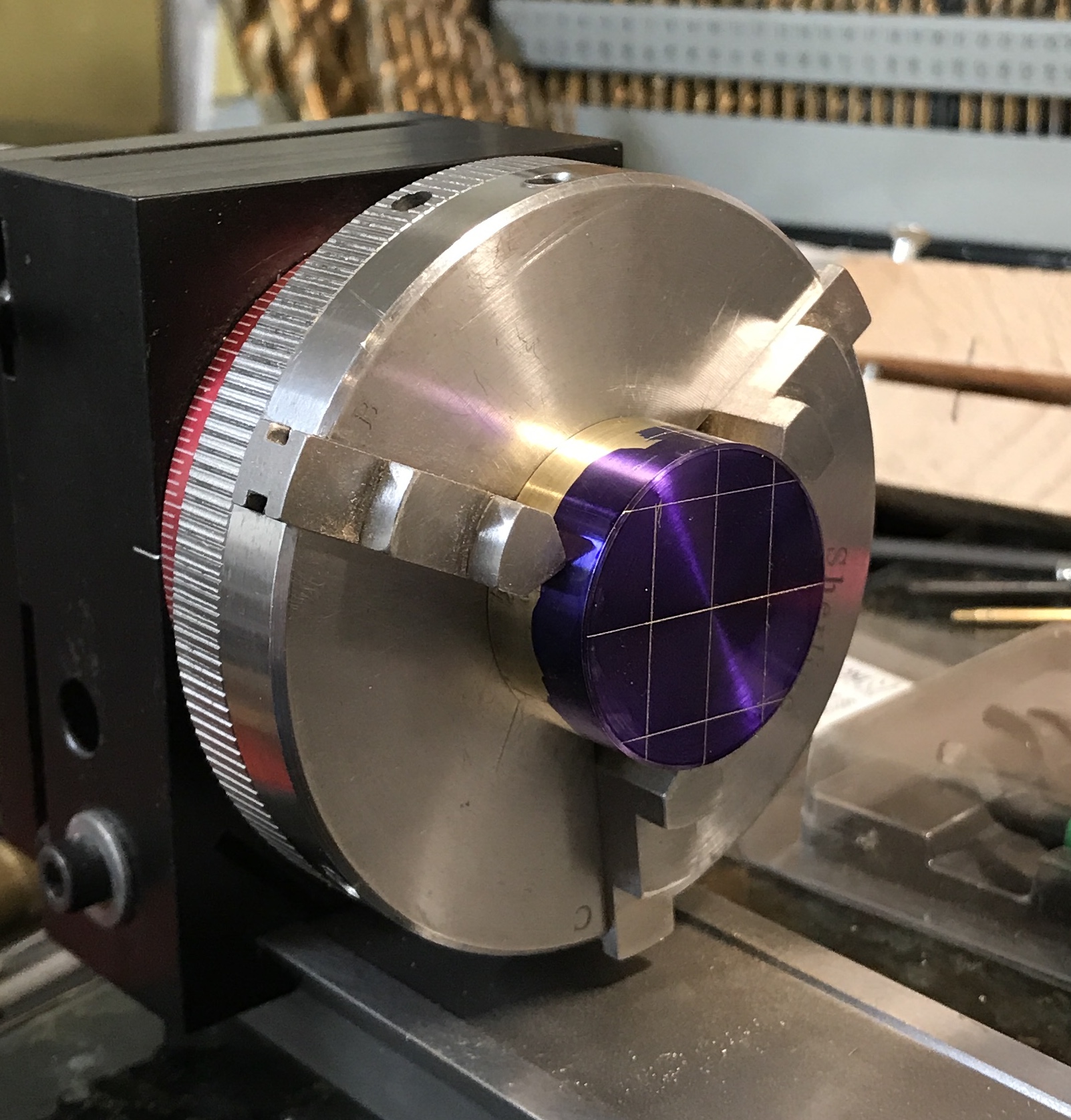
A 1/2" X 1 1/8" X 3" bar of bronze was squared up. The thickness was reduced to 0.40" with a lot of effort. The width was reduced to 1.04". It was cut in half with a hacksaw giving two 1 1/2" bars. After all sides were square and flat the holes were marked out. Two tapped 4-40 holes were made in the bottom for attachment to the tablature. A #43 drill was also used to drill a hole from the top. The hole for the shaft was drilled and bored to 1/4" for use on the rotary table. The length was reduced to 1.25" with a hacksaw. One part was put on a 1/4" shaft in the centered rotary table. The table was moved off center by 0.656" (0.5" + 5/32"). The semi-circle was cut in 0.010" deep passes until the last 0.020" were cut all at once. This was repeated on the second bearing. The oil holes were re-drilled through to the center hole and tapped 4-40.
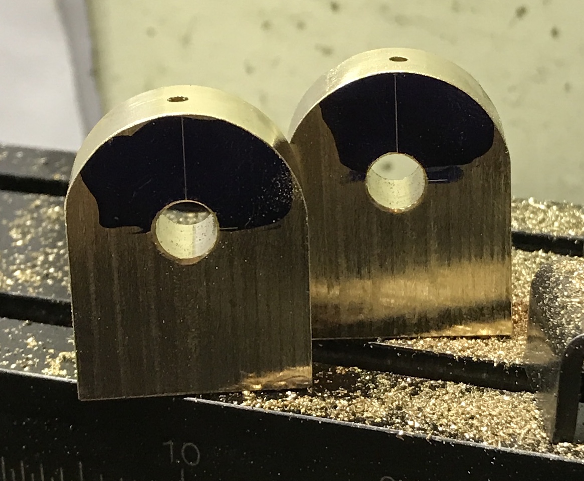
Drilling the center hole out to 7/16" was challenging. I could drill up to 5/16" in the mill. The mill just didn't have the power to go further. So I switched to the small drill press. Its belt was set on the lowest speed. The bearing was held in the mill vise on parallels. The vise was held by hand. The drill size was increased in 64th's. Cutting fluid was used. In this way I was able to drill up to 27/64" or 0.422" leaving ample metal for the reamer. The picture below shows the two completed bearings (except for the final reaming in place.) The oil holes were retapped.
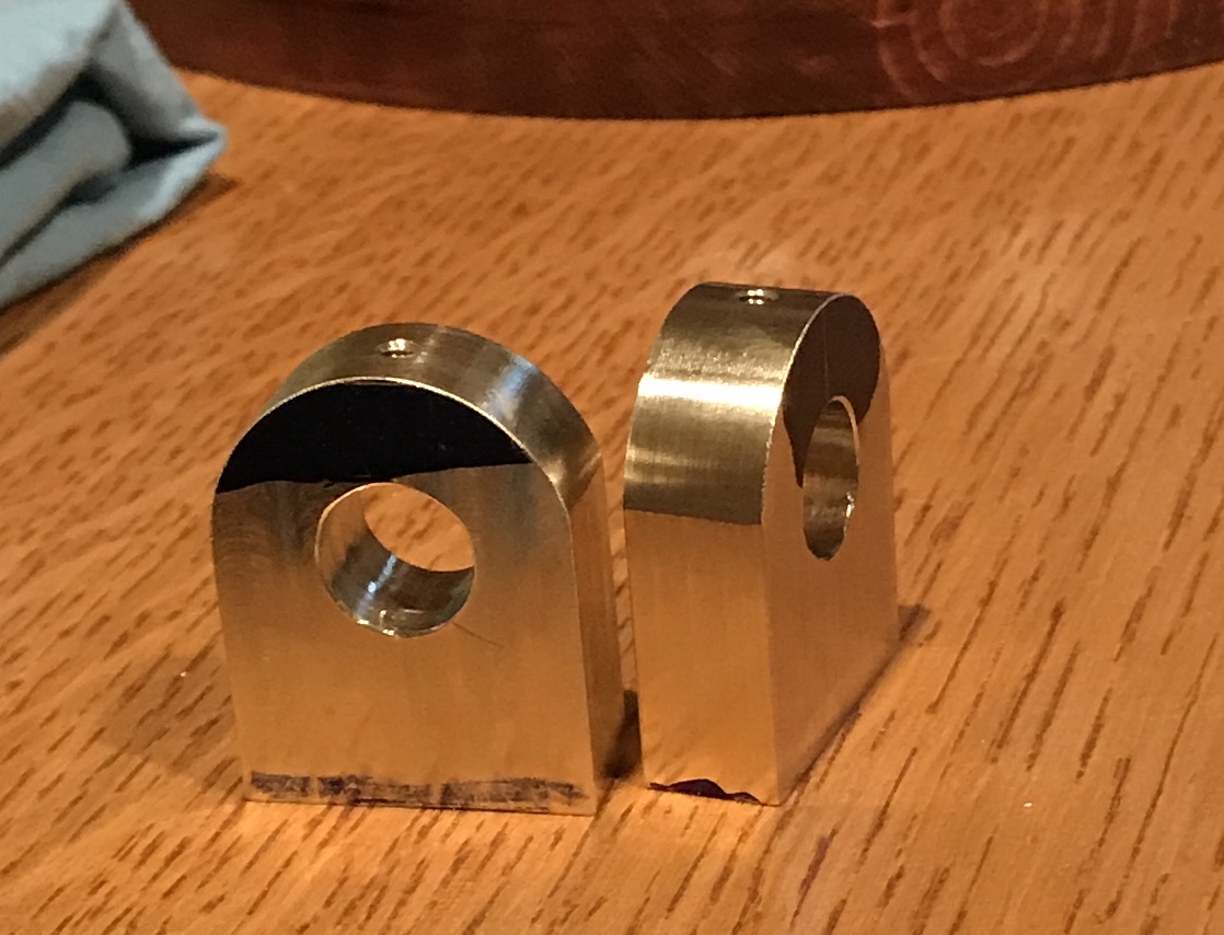
The bearings were marked. A single punch mark was placed on the "front" bearing on the outside of the bottom. Two punch marks were placed on the inside bottom of the "back" bearing. The screws available need to be shortened by about 1/8". The bearings were attached. I was unable to push the 27/64" drill through both bearings. Checking the two bearings with a square indicated that the two are not aligned!!. They are shifted relatively along the long axis of the entablature by 1/64-1/32". After sleeping on it I realized a different explanation for the misalignment existed. I turned the rear bearing around and now all is well. Whew!! The third sentence above was changed to reflect the correct orientation of the bearings.
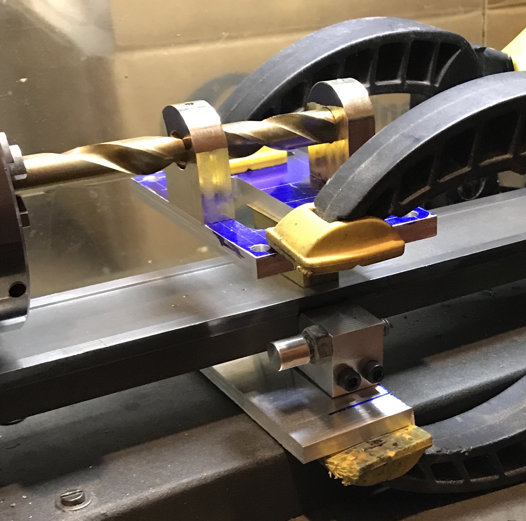
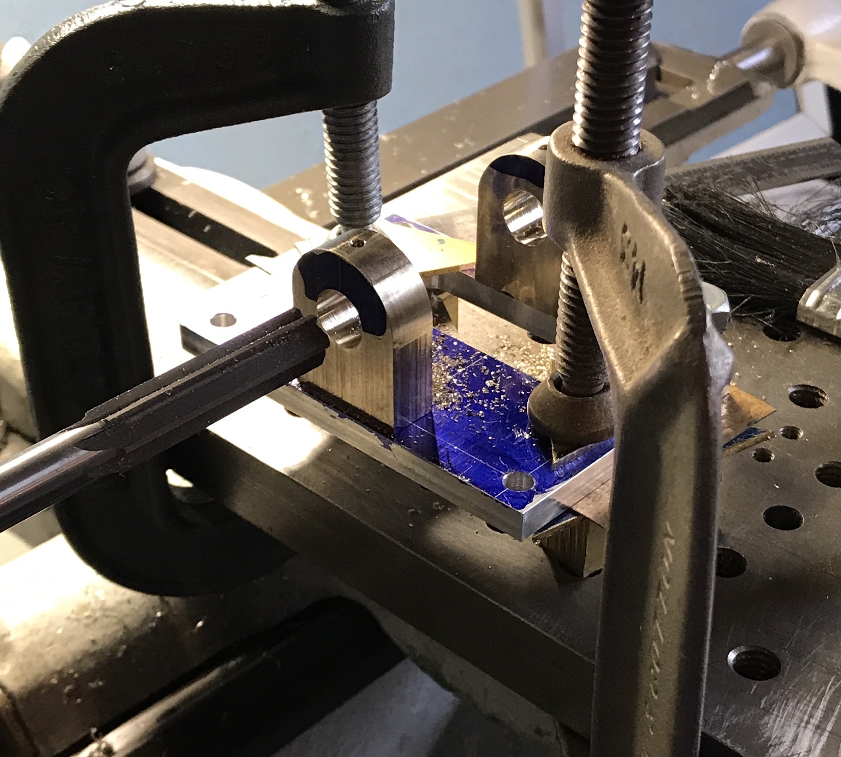
The bearings need to be reamed in place. The cross slide cannot be used as it is too high. With both attached the 27/64" drill can be inserted through one and into the next, but not all the way through. The other end of the drill was clamped in a three jaw chuck on the lathe. placing a 3/4" block of brass under the entablature along with a 1/32" strip of brass vertically centered the bearings. With the lathe stop serving as a clamping platform beneath the lathe bed, two clamps could be applied to the entablature and a piece of aluminum beneath the stop. This leaves two problems: the drill cannot be removed and the 7/16" reamer cannot be installed. The picture below shows this less than ideal setup. I will have to use the South Bend in the cold garage.
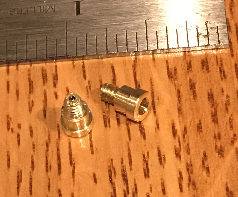
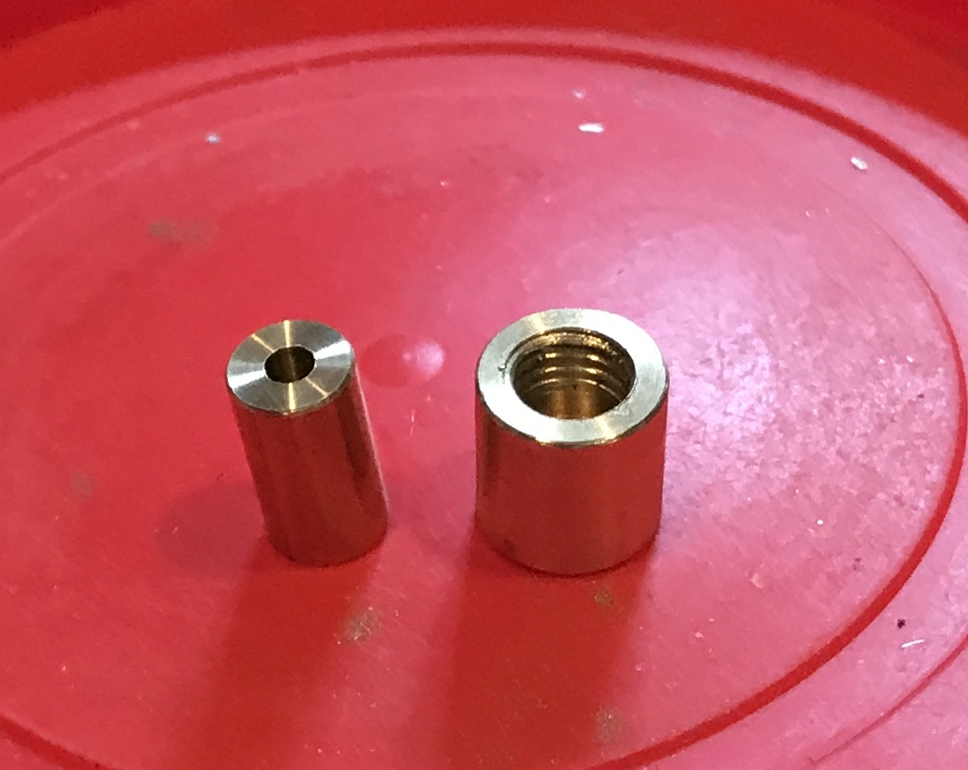
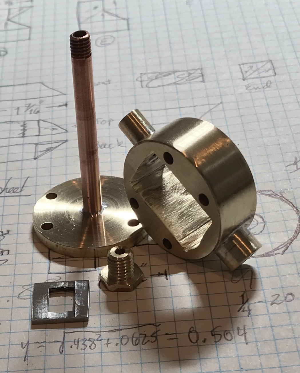
While waiting for some warmer weather the oil cups for the bearings were made. A 1/4" rod of brass was chucked in the lathe and 0.320" was reduced to 0.19". Of this 0.22" was further reduced to 0.16". Finally, 1/8" of this was further reduced to 0.112". This 1/8" was threaded with a 4-40 die in the tailstock die holder. The part was parted off at 0.28". A split nut was prepared, screwed onto the threaded end of the part and held in the lathe. It was aligned by eye with light taps. A #0 center drill was used to just spot the face. It was drilled through with a #60 drill and drilled 1/8" deep with a #42 drill. After deburring both parts were completed and are shown in the photo.
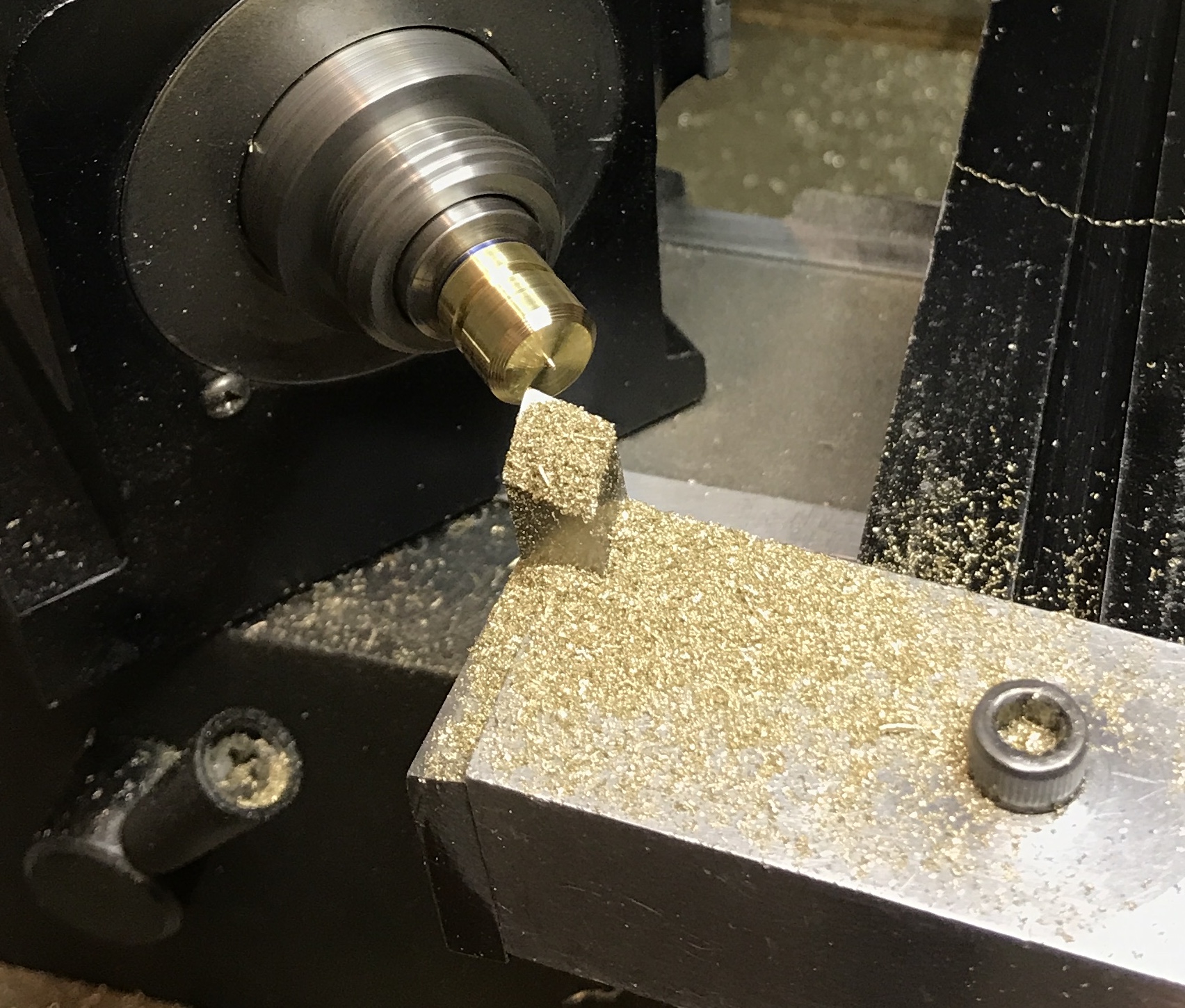
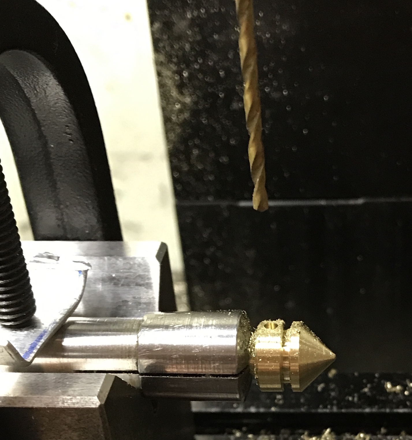
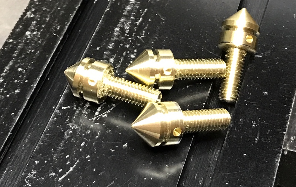
Made the four brass cap screws this morning. Two 2 1/4" lengths of 3/8" brass hex were cut with a hacksaw. After chucking one in the three-jaw with 1" exposed it was turned to 3/8" diameter for 15/16". The first 1/2" was reduced to 0.190" and threaded 10-32 with a die in the tailstock die holder. A groove was cut at 5/8" with the cutoff tool to 0.05" deep. Edges were slightly chamfered and the part was cut off. All four parts were finished to this stage. The threaded end of a part was held in a 3/16" collet in the lathe. The headstock was rotated about 48° and a cone was cut on the end of the part. The little bit of a nub from parting was filed round. The collet with part was removed from the lathe and held in a V-block on the milling table. The spindle was centered over the 1/8" wide section just beyond the threads. It was centered in the orthogonal direction using a ruler. A small dimple was made with a #0 center drill and then a hole was drilled 0.09" deep with a #52 drill.
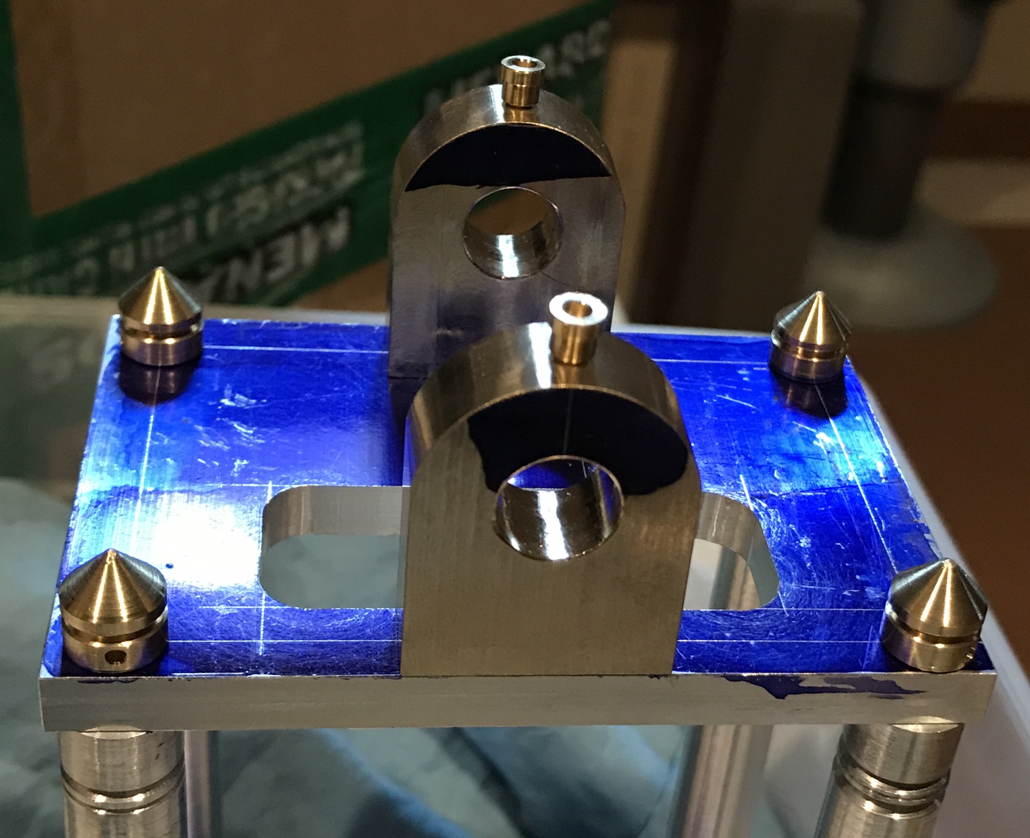
The first two photos show the setup for milling the cone and drilling the hole. The second two photos show the four completed cap screws and the entablature at this stage of machining.
Attempted boring the bearings in place in the mill. It was a no go. Even with the entablature sitting on the table there was not sufficient room to put the reamer in the chuck and still remain above the highest bearing. So it is off to the cold garage. The compound was removed by loosening the two screws that are also used for rotation. The previously made cross slide plate was put on and tightened in place. The drill was inserted into the bearings and the free end was held in the three jaw chuck. A quick measurement showed the bottom of the plate was slightly less than 7/8" above the cross slide plate. A nice fit was discovered: 3/4" brass blocks, 1/16" brass scrap plates, and etc. The drill was removed and the reamer was placed in the chuck. The first bearing was reamed, but when the reamer was advanced to the second bearing it was not well aligned. The entablature was rotated slightly and the second bearing was reamed. When the reaming was stopped partway through the reaming looked even around the hole. Won't know for certain if this was successful until the the shaft has been made and inserted.
The crankshaft assembly consists of three parts. I began with the crankshaft. A length of 1/2" steel rod was cut to 3 11/16". This was held in the chuck with a steady rest. It was indicated to < 0.001" runout. The end was faced and center drilled. The rod was removed, measured, flipped, and indicated. The shaft was faced to 3.625" and center drilled.
The crankshaft was held between centers and most of its length was reduced to 0.438". The crankshaft was checked for fit in the assembled bearings as the diameter was reduced. The last few thousandths were removed by sanding with 100 and 150 grit paper. The fit in each bearing was a nice running fit, however there was binding when inserted through both bearings. One end was further reduced to 0.375" for 1.031". The opposite end was also reduced to 0.375" for a length of 0.219". The rod was "polished" with crocus cloth.
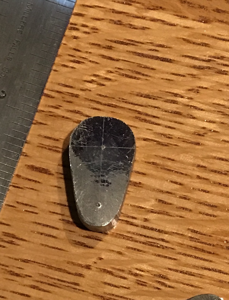
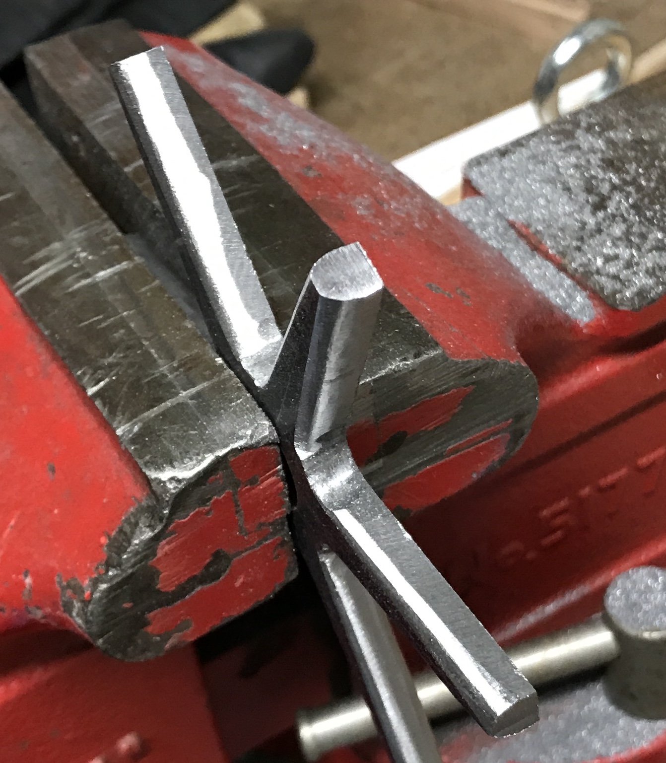
A 1" length was cut from a 1/4" X 5/8" bar of steel. It was painted with Dykem and three lines were marked: a center line at 5/16", a line 0.210" from the bottom, and a line 0.710" from the same end. A prick punch was used to mark the intersections. A semi-circle of radius 0.19" was drawn around the bottom hole and a semi-circle of radius 0.28" was drawn around the top hole. The semi-circles were connected with straight lines forming the outline of the crank. The corners were removed with the sanding belt. A file was used to remove all metal outside the lines. It was over an hours worth of filing. The resulting shape is seen in the photo below.
The crank was center drilled and drilled with a #21 drill. It was tapped 10-32. When the part was placed in the four jaw chuck, I realized it needed something to support it during drilling and facing. A lathe spider was made out of a scrap aluminum gear. The spider design was laid out on the gear. A 1/4" radius circle was drawn followed by four legs. The sides of the legs were cut with a hacksaw. To remove the wedges between the legs holes were drilled with a 3/16" drill. The wedges could then be wiggled out. The bottom areas between the legs were filed to shape. The first picture below shows the completed spider. It was placed behind the crank (along with a scrap of 1/16" brass) and the punch mark for the 3/8" hole was centered with the aid of a tailstock center. The hole was center drilled, and drilled up to a T drill. The hole was reamed 3/8". The crank was faced to 0.219" and further faced to 0.188" leaving a 0.438" diameter thrust shoulder. The completed crank is also seen below.
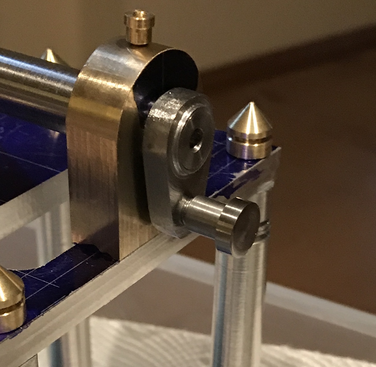
The crank pin was made this morning. A 2" scrap of 3/8" steel rod (probably drill rod) was chucked in the three jaw and 0.532" was turned down to 0.250" This was polished with crocus cloth. The first 0.188" was then turned down to 0.19" and threaded 10-32. All shoulders were chamfered and the part was parted off. It was held in a collet and the parted face was cleaned up and polished as well. Similar to the cap screws, the crank pin was drilled 1/16" from the end. First it was center drilled and then drilled with a #52 drill. A 1/16" diameter pin was cut and the ends filed to use as a Johnny bar. The crank pin is shown below installed in the crank.
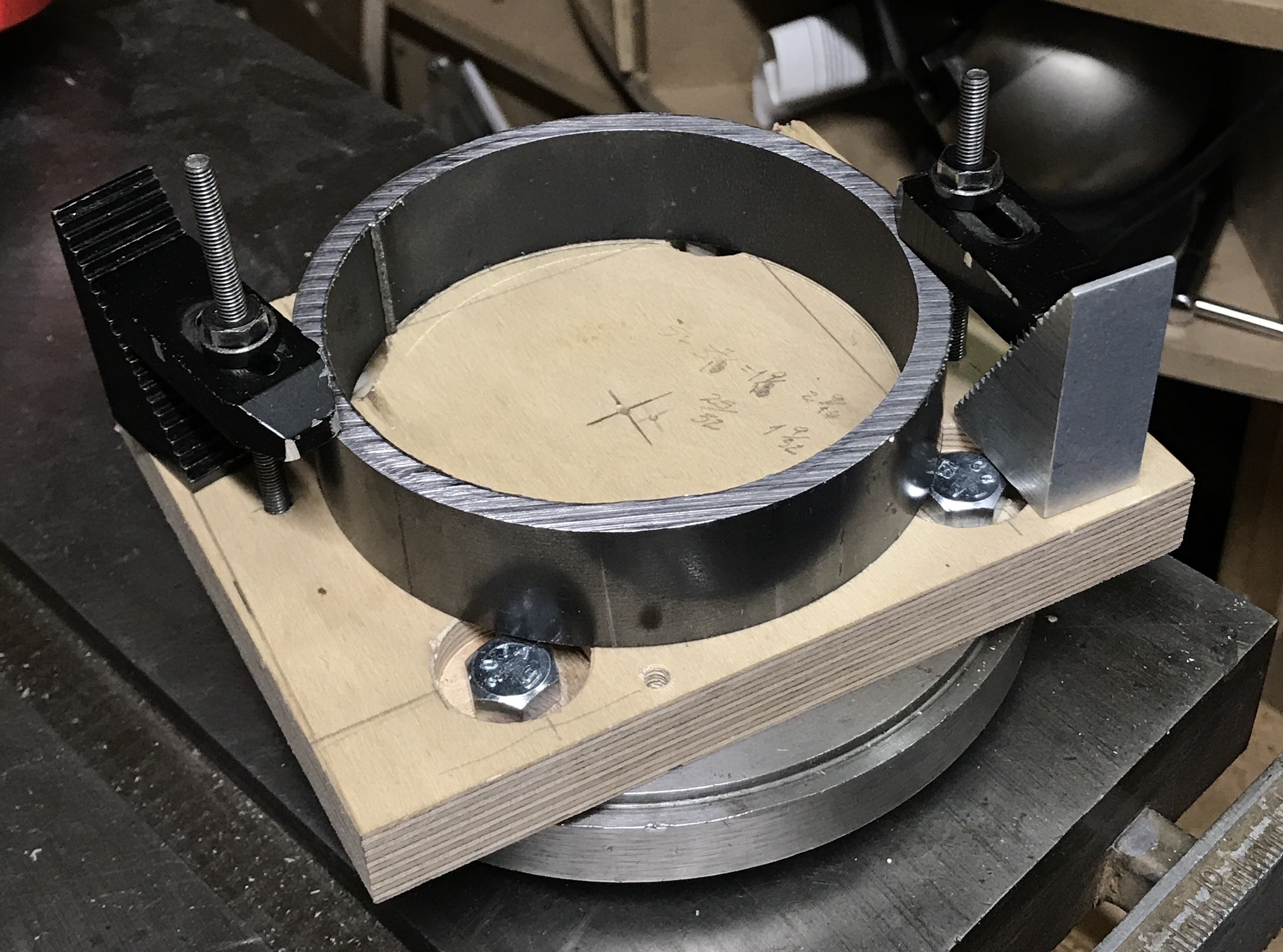
A means of clamping the steel pipe to the South Bend faceplate was required. A square of plywood was cut to size. The four mounting holes in the faceplate were transfered to the plywood. They were drilled 3/8" and opened up to 7/16". They were also countersunk with a 1" Forstner bit. Four 3/8-16 bolts were found to attach the plywood to the faceplate. Four holes were marked out to use the Sherline strap clamps. These holes were drilled with a #21 drill and tapped 10-32. I only have two strap clamps. These are shown installed with the 1" section of 4 1/2" steel pipe. With luck two clamps will be sufficient for boring.
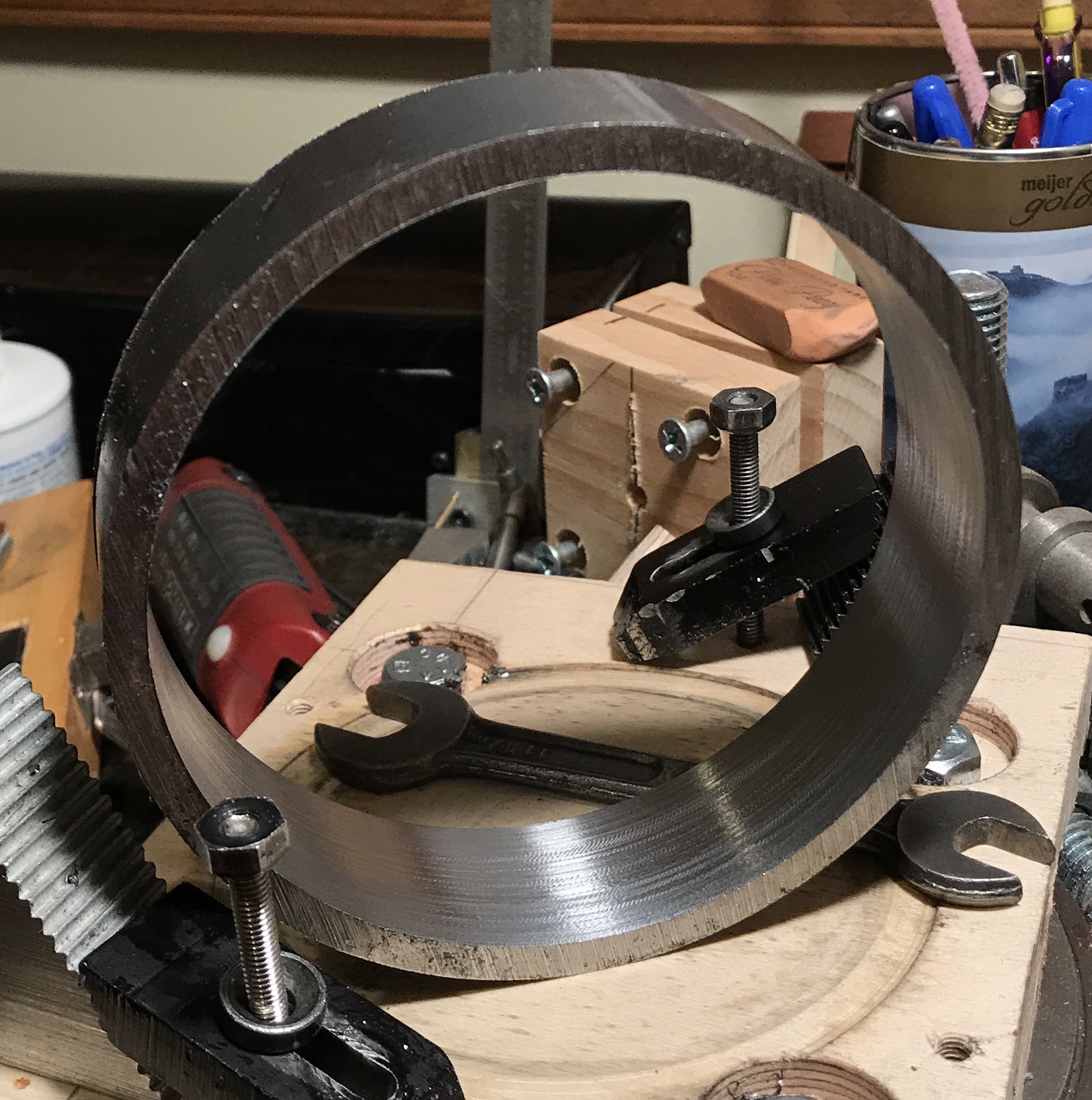
After switching to shorter studs the face plate was put on the spindle. The dial indicator was used to get the ring close to center; within 0.010". The boring bar was used to take light cuts: 0.005-0.010". There is a ridge at the weld location. This was removed first and then about 0.050" total was removed. There was some chatter. The inner face was lightly sanded. The bore gauge measured the ID at 4.087". The wheel at this stage is shown below.
The wheel hub was made from a length of 1" diameter steel rod. 1.031" was reduced to 0.750". Then 0.656" of this was further reduced to 0.620". (Note discrepancy from plan! Should not be a problem as spokes are bored to fit.) The small end was faced and the other end was cut off and faced to 1.031". The hub was drilled up to a T drill ready for boring after installation.
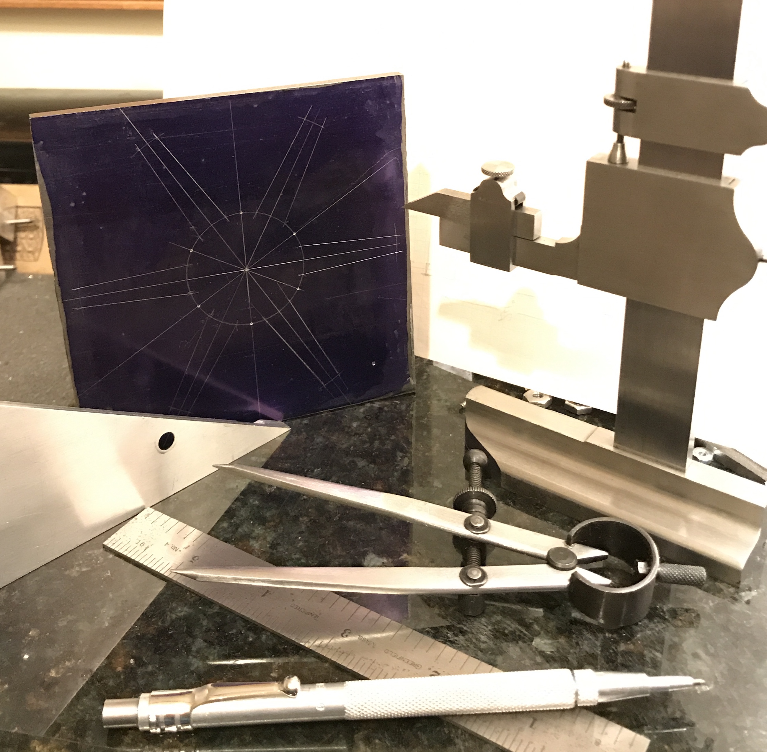
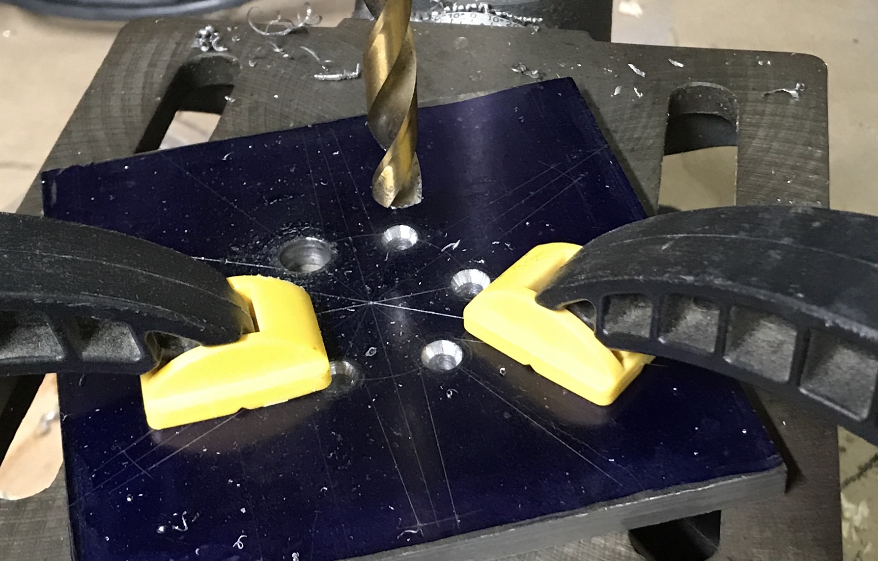
The spokes were laid out on a 1/4" X 4 1/2" X 4 1/2" steel plate. Dykem steel blue was painted on one face of the plate. One corner was punched to denote that it was the most square of the four. The center point was found and punched. A 0.75" radius circle was marked. The angles of the legs and drill holes were found with the aid of the 30°/60°/90° triangle used to align the vise on the milling table. The intersections of every other line with the circle were punched to indicate these locations were the centers of the holes separating the spokes. Arcs of a 2.06" radius circle were marked on the lines for the legs (between the lines for the drilled holes) denoting their ends. The picture below shows the completed layout and some of the tools used.
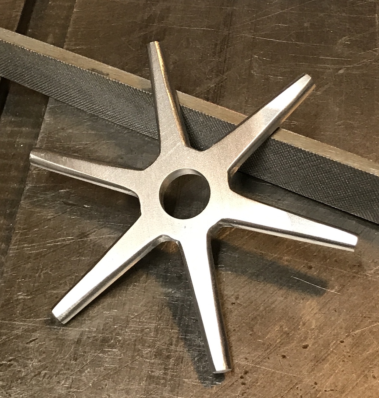
The six holes were drilled first. These were first drilled with a large (#2?) center drill and then drilled with a 3/8" drill. The holes were deburred. The legs were cut with a hacksaw. Twelve long cuts later the six-spoked part was roughly cut out as seen below. The spoke ends were cut off a little long prior to lathe work.
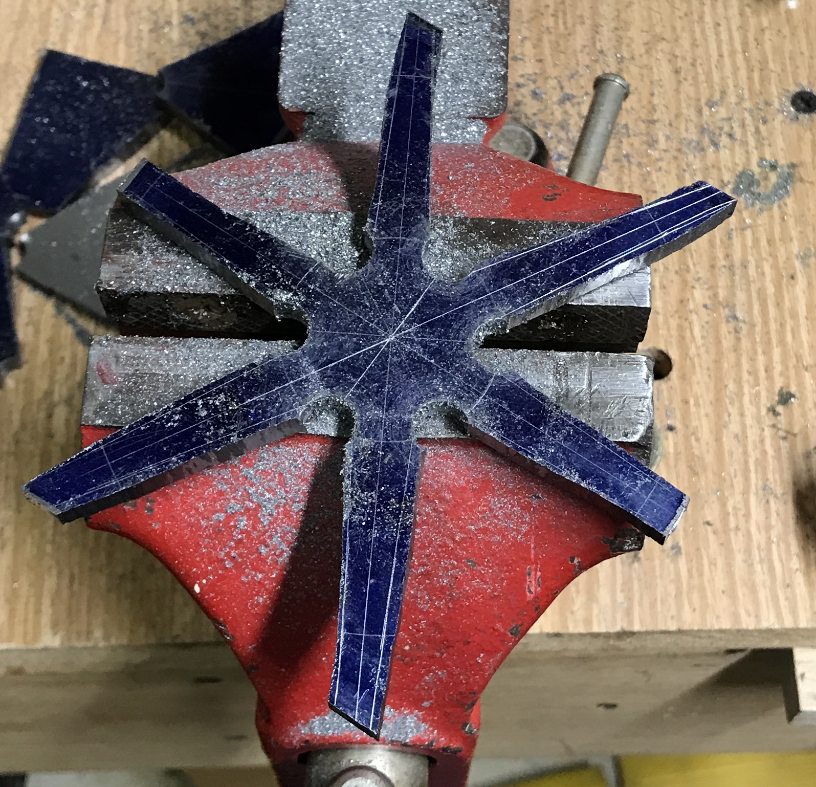
Picking up the wood for Sandy/Erin/Mack's shelves this afternoon at Menards. The shelf project may delay further work on the overcrank engine. After two weeks the box shelves were completed. It is time to return to this engine. The roughly cut out spokes were filed. About 5000 file strokes later the spokes are close to desired. They will be rounded later. The picture below shows the spokes at this stage.
Froze my toes in the 30° garage this morning. The next few steps on the wheel had to be done on the South Bend lathe. I centered the spokes on the wooden faceplate adapter. With the aid of two new tapped holes the spokes were clamped close to center. The faceplate was put on the spindle and a tailstock center was used to make a final centering adjustment. The center hole was center drilled, drilled 1/4" and then with a series of drilles up to 1/2". It was then bored in 0.015" increments to fit the wheel hub.
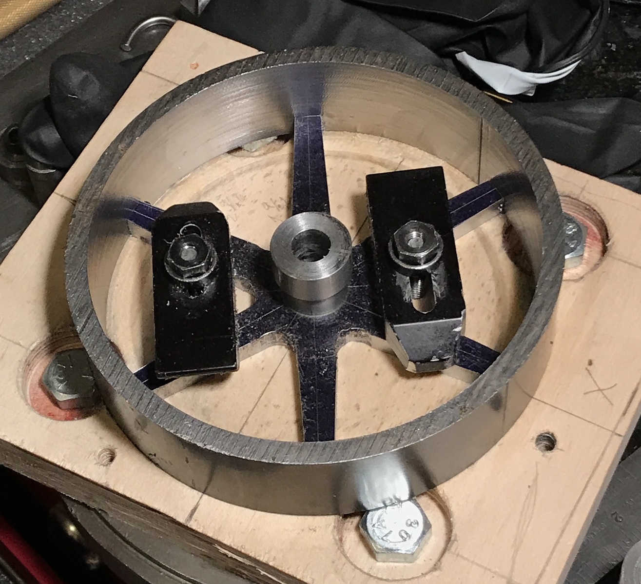
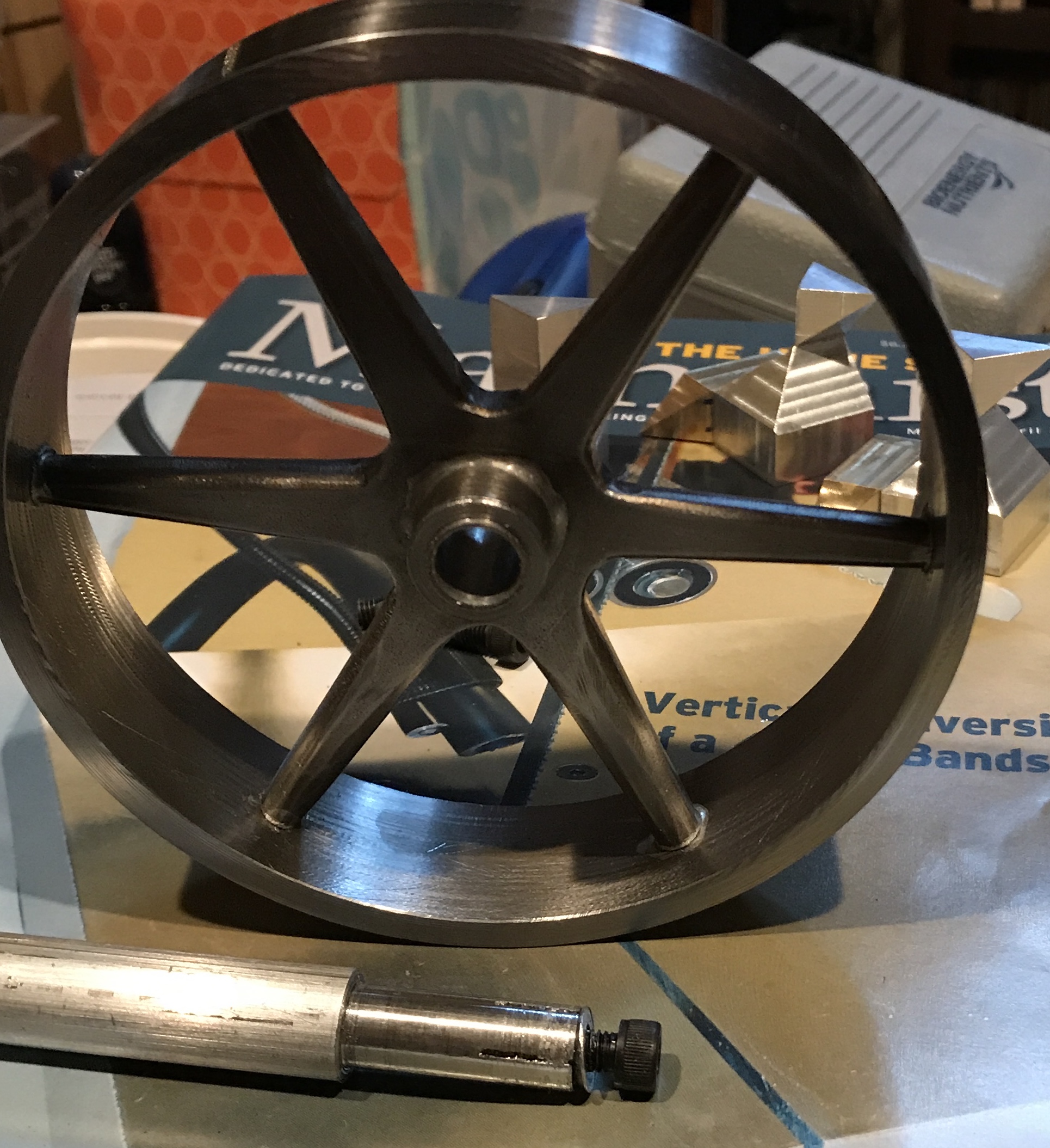
A turning tool replaced the boring bar and the ends of the spokes were cut in 0.010" increments. The cutting went smoother than expected for this interrupted cutting. The rotation speed was about 900 and this slow speed may have helped. In any event the spokes are a nice fit in the wheel. The first picture below shows the hub inserted in the spokes and the spokes inserted in the wheel. The second is just a mockup of what the final wheel should resemble after soldering.
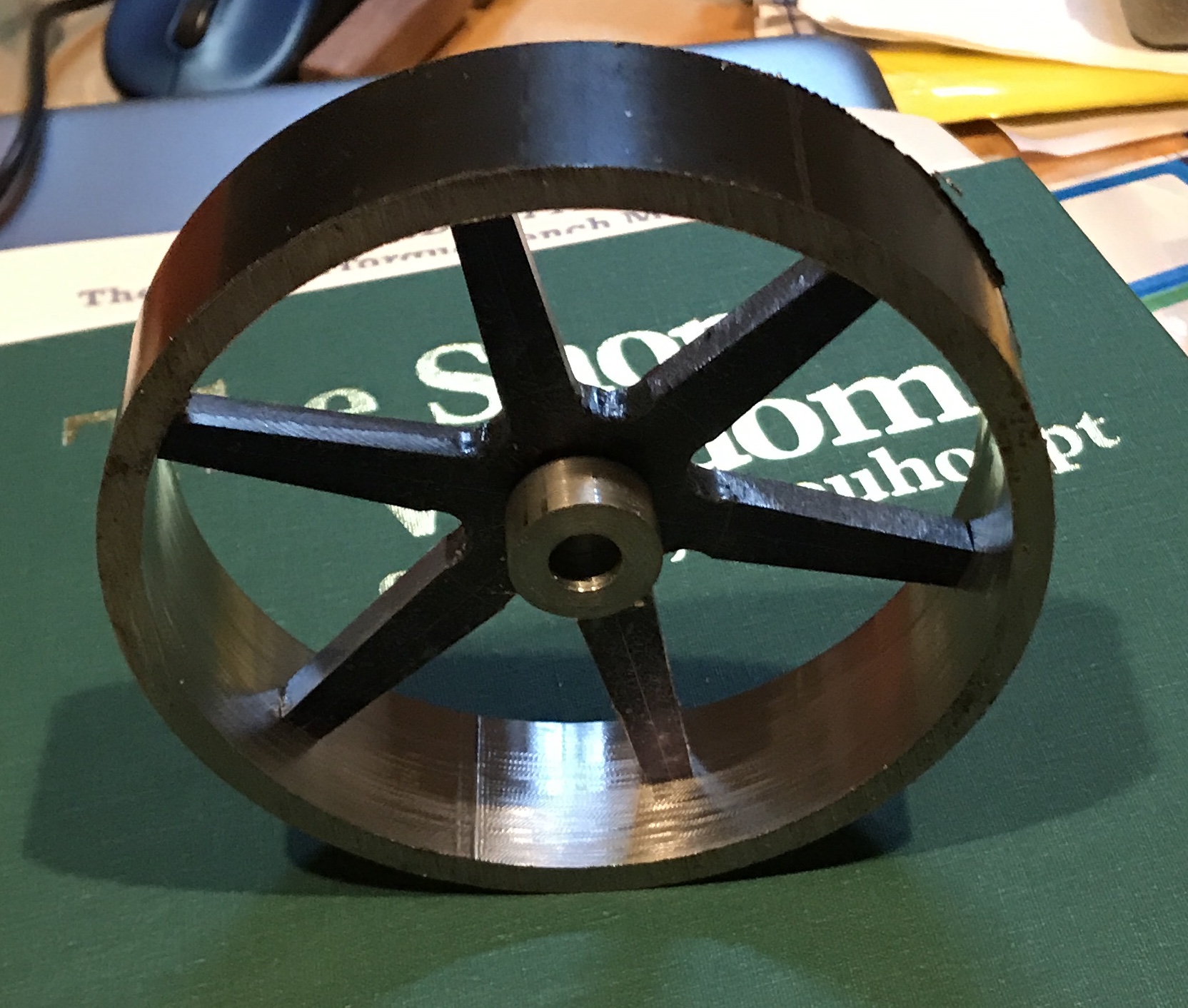
The width of the wheel is 1 1/16". To center the spokes they need to be lifted 13/32". A flat disk of steel was found in the scrap box. It was faced in the lathe to 13/32" thick. This disk nicely centers the 1/4" thick spokes for soldering. But first the spokes need their corners rounded with a file. So it is back to the vise. Tried to use the belt sander. Got a splinter in the eye. Lots of rinsing at home and a brief trip to the optometrist. A little scratch that quickly healed. The belt sander didn't even work! Almost finished the filing as seen in the photo below. Six corners left.
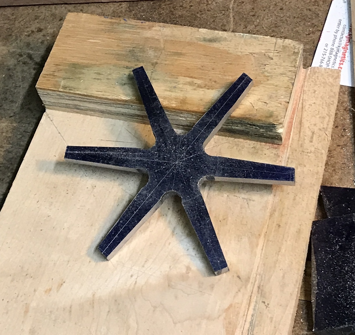
The final corners were finished giving all six spokes rounded ends. The gaps between spokes were filed with a round file and rough edges removed. The two faces of the spokes were then sanded with 180 grit paper. This sanding left a nice matte finish. The photo below shows the completed spokes.
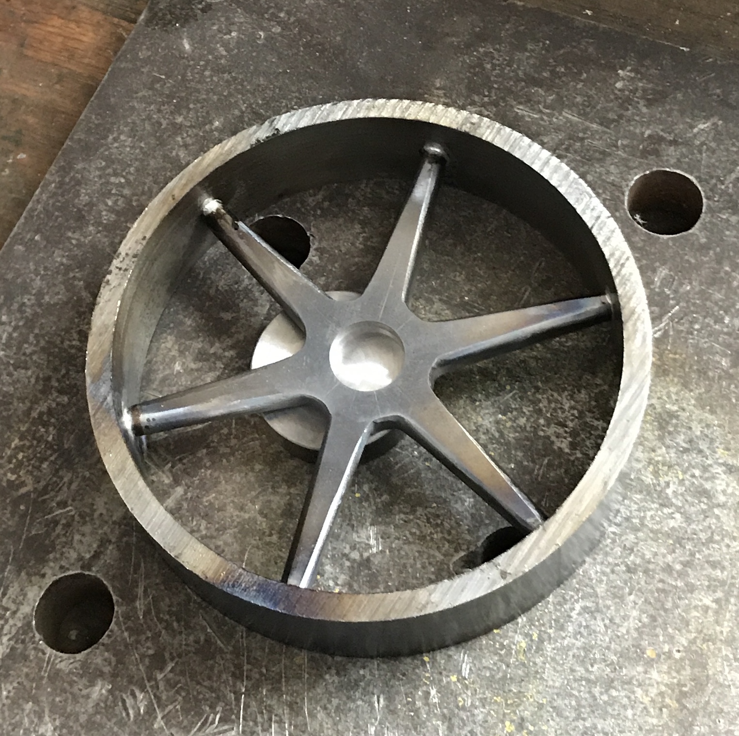
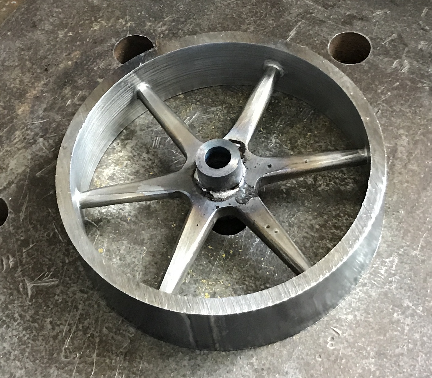
Took a 3/4" thick steel plate to the garage this morning. The spokes were set on the spacer inside the pipe resting on the steel plate. A drop of flux was placed at the juncture of a spoke and pipe. A paper towel was kept underneath this spot until ready to heat. A small piece of solder was placed on the join. The outside of the wheel was heated for 15-20 seconds. Then the inside was briefly heated and the solder flowed into the joint. The photo below shows the six spokes soldered to the pipe. After cooling any remaining flux was rinsed off and the wheel dried. A little sanding cleaned up the spokes and wheel. I forgot that the hub also needs to be soldered in place at this time. So it was. It was soldered first on one side then on the other. Rinsing and sanding proceeded as before. Rubbed a few drops of oil to prevent rust.
The wheel was attached to the face plate with two strap clamps. The wheel was first centered with a tailstock center and then trued up with a dial indicator. The clamps were tightened and one edge was faced in the frigid garage. Turning the outside of the wheel was a nightmare. The tool kept digging in even with 0.005" cuts. This knocked the wheel off center. Decided that the black layer on the outside of the pipe was the problem and removed it with a file. The turning went better but still dug in. Gave up for the day.
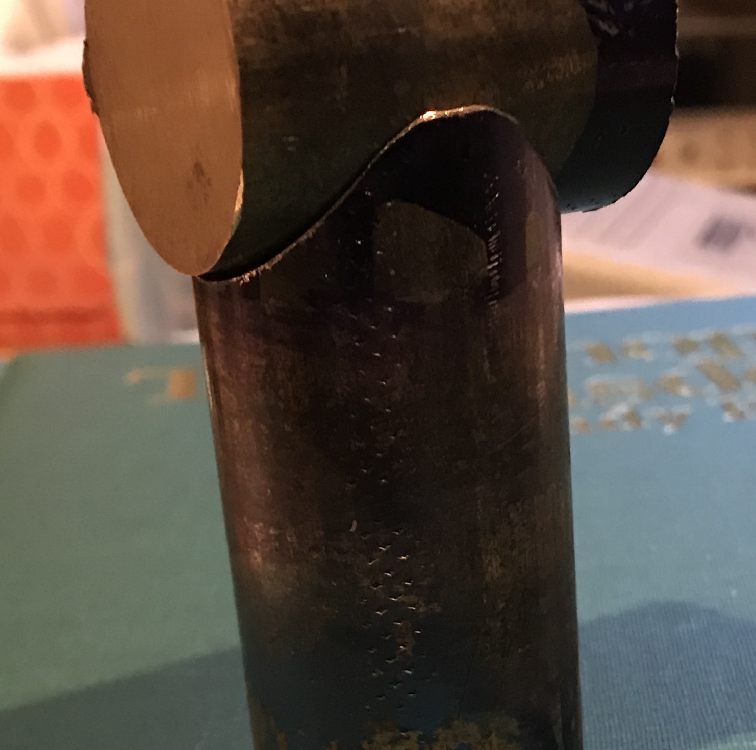
At it again the next morning. The studs are just screwed into the wood and might be coming loose during the interrupted cutting. They were locked in place with extra nuts. Still not an easy cut, but got it finished. The center hole was reamed and then the wheel was flipped over and centered as before. The edge was faced with light cuts and the corner was chamfered with a file. I was not able to cut the shoulder on the hub. The back of the turning tool hit one of the nuts during a test spin. I will need a 1/4" tool to fit. Stopped for the morning to warm up. The photo below gives an indication of the issue.
After taking a walk I was still warm so I spent a few minutes cooling down in the garage. The 3/8" cutting tool was replaced with a 1/4" tool on a 1/8" spacer. This worked well and the shoulder was cut 1/32" deep leaving a 0.438" OD. Chamfered the external corner of the wheel with a file and called it quits for the cold garage work. The wheel and hub were cleaned up with a few different files. The photo below shows it in place on the shaft. The wheel does not run true. Both it and the shaft require some repair work. The wheel will eventually be painted. It was coated with a light coat of oil to prevent rust.
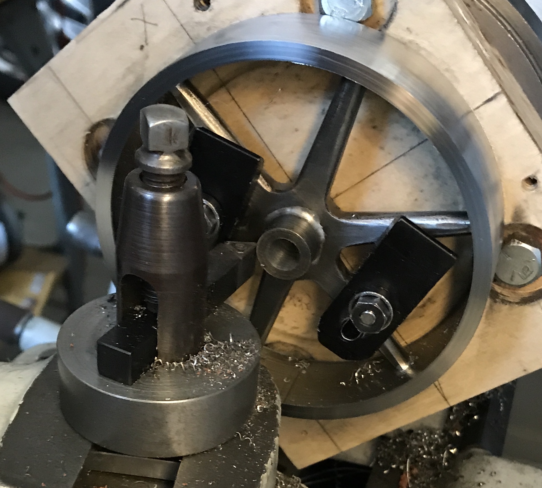
We are seeing some warmer weather late in February, so I plan to get back out in the garage. The wheel needs to run true. In order to recut the wheel I need an arbor to hold it securely in the lathe. A 1 1/2" length of 3/4" aluminum hex was cut with the hacksaw. It was faced on both ends. One end was reduced to 0.41" for 1 1/32". This same end was center drilled, drilled with a #7 drill, countersunk (80°), and tapped 1/4-20. It was drilled about 1" deep. Two slot were cut in this end of the arbor. A 1/4-20 flat head screw was cut off about 1" long. The screw was screwed into the arbor and it was returned to the lathe. The reduced portion was further reduced to 0.375". The screw head was larger than 0.375" and was reduced as well. The photo shows the arbor installed in the wheel's hub.
I was unable to tighten the screw in the arbor sufficiently to hold the wheel tight enough. The phillips head would just slip and tear up the screw. I need a socket head flat screw, but do not have any. The alternative is a wedge driven in by a socket head cap screw. Of course I do not have a 1/4-20 SHCS.
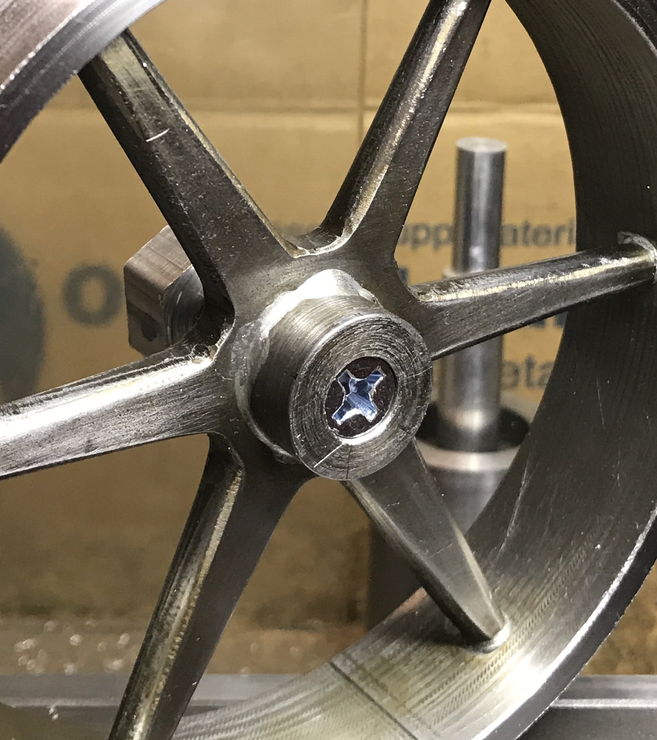
A second arbor was made. A 4" length of 1/2" aluminum rod was faced and reduced to 0.375" for a length of 1.05". It was drilled and tapped 10-32. A deep countersink was made with an 82° countersink. The end was then cut about 3/8" deep with a hacksaw in two perpendicular directions. The part was returned to the lathe with the unmachined end exposed. It was faced and reduced to 0.375" for 1/2". It was drilled 0.199" as a through hole for the screw. The head was turned 41° and the end was cut until the hole was reached. After returning the head to its normal position the tapered part (3/16") was parted off. The arbor worked well, though the sides of the wheel were never completely aligned with the axis of the wheel. The wheel is too flexible. The outside of the wheel was sanded to 320 grit for a decent finish as seen in the photo below next to the arbor.
With the wheel complete the next sub assembly to tackle is the steam chest. This began with the steam chest cover. A 3/16" length of 1.25" brass rod was cut off with a hacksaw. It was faced on both sides and thinned to 0.125". Both sides were sanded. The hole locations were laid out. The disk was returned to the lathe to drill the 3/16" center hole. The remaining four holes were drilled on the mill with a #33 drill. The steam pipe was made next from a 3/16" copper rod. After cutting a 2" length the rod was held in a collet in the lathe. It was faced and threads were cut on the end with a 10-32 die for 3/16". The rod was then drilled half-way through with a 0.120" drill. (I am not sure of the correct ID for a 3/16" pipe, but figured 1/8" was probably close.)The rod was flipped end for end in the collet and drilled the remaining 1". WD-40 was used liberally during the drilling process. The outside was lightly sanded with crocus cloth. The picture below shows the two parts assembled but not soldered.
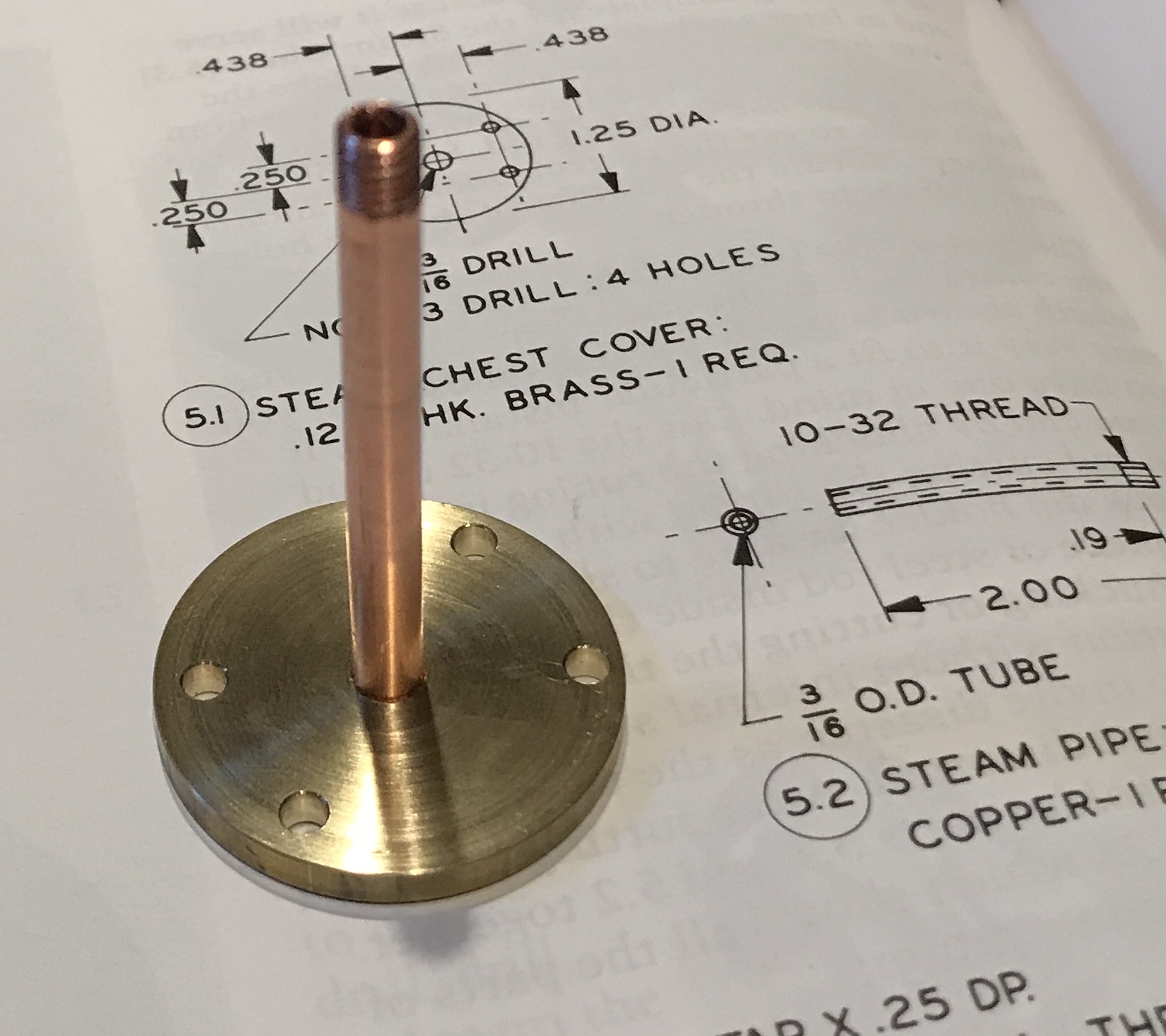
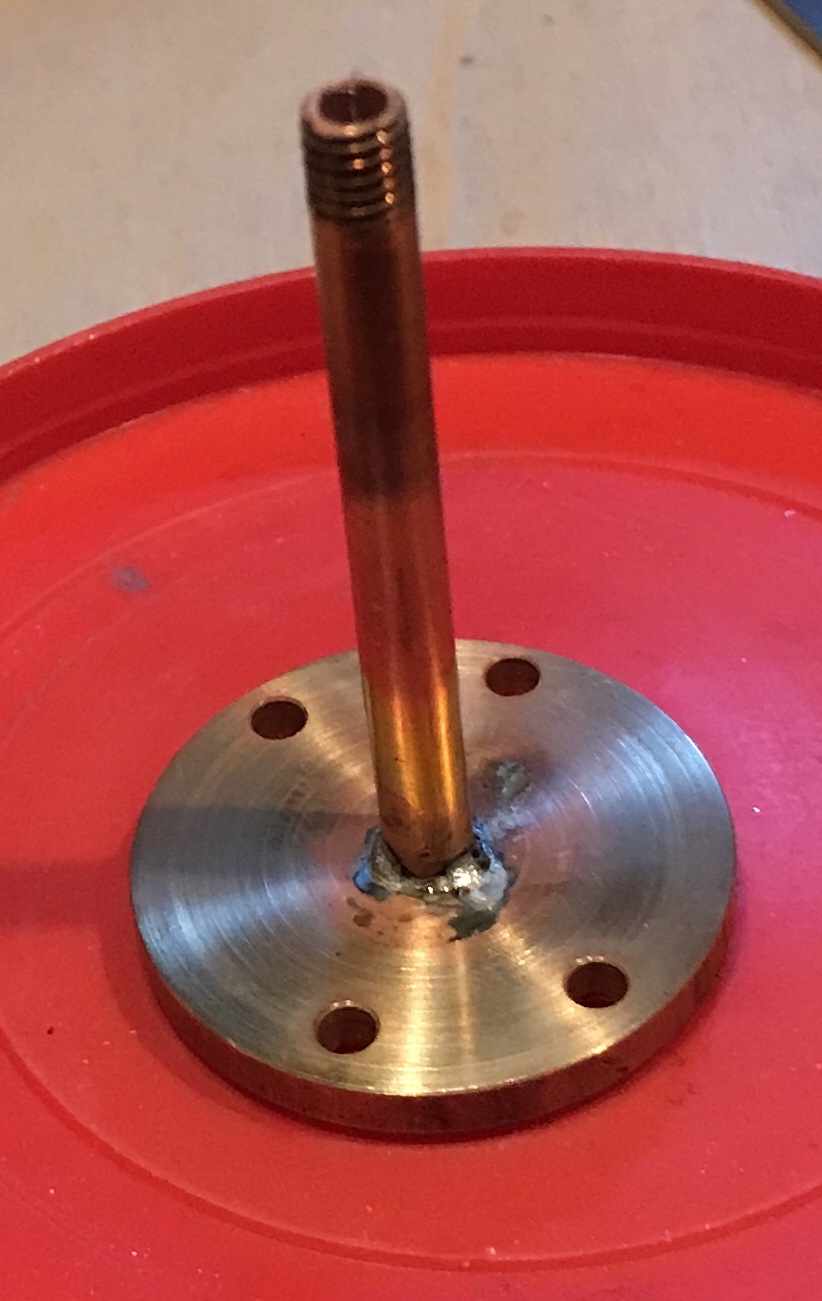
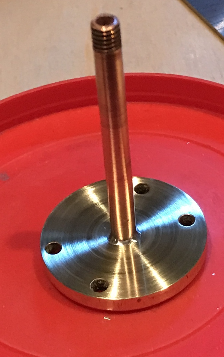
Soldering was straightforward. Three tiny pieces of solder were placed around the the steam pipe after setting it in the cover. Flux was applied and the cover and pipe were heated with the propane torch. The solder flowed into the joint. After cooling the cover-pipe unit was returned to the lathe and cleaned up with sand paper and crocus cloth. The photos below show the soldered and cleaned up unit.
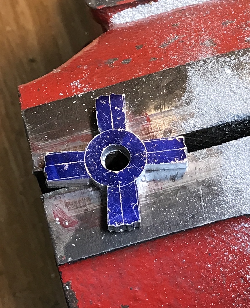
The steam chest was a 7/16" cutoff from the same brass rod as the cover. It was faced on both sides in the lathe and reduced to 0.500". The faces and the circumference were sanded to 1000 grit paper. Bluing was painted on one face and the disk was mounted in the chuck on the dividing head. The center of the dividing head is 1.75" above the top of the bed. A center line was scratched using a 1-2-3 block and the aluminum scratching block. The head was turned 90° and a second center line was scratched across the disk. One line (now it is the vertical) was extended to the sides. Using alternate heights the outline of the cutout was scratched as well. The photo below shows the completed marking out on the face.
The steam chest was held in the vise with the horizontal line parallel with the vise top. The spindle was aligned with the mark and it was center drilled and drilled 1/4" for about 0.2". The part was rotated 180° and realigned. It was center drilled, drilled 1/4" and drilled 3/8" again about 0.2" deep. The part was then set on 1/4" packing on the angle plate. It was drilled through with a series of drills to 3/8". It was drilled in two places to remove most of the opening waste. A 3/16" end mill was used to remove waste to the line. Unfortunately, it was too short to complete the last 0.05" so a longer and larger end mill was used to finish the job. It jumped in one corner and left a noticeable impression. The corners were filed with a square file and with a flat file. The front face was sanded to 2000 grit. The drilling/milling setup and the finished product are shown below.
The valve stem bearing was made from 1/4" brass rod. A 1/2" length was cut off with the hacksaw and faced in a collet. It was flipped end for end and faced to length, 0.44". It was drilled 0.375" deep with a #42 drill. The drilling got progressively more difficult as drilling proceeded. The ends were lightly chamfered. The stuffing box was made next from 3/8" brass hex. I could not find 0.375" rod. A 7/16" length was cut with a hacksaw and faced in the mill. It was reversed and faced to 3/8". It was then turned down to 0.375". Attempts were made to drill the #42 hole through, but no chips were formed. The drill was completely dull! I was unable to sharpen it by hand. I have 20 #43 drills and 9 #41 drills in the horde, but no #42's! Ordered this size drill and a few others. Should arrive tomorrow. Finished the stuffing box by drilling through with the new #42 drill and then drilling 0.25" deep with a #3 drill. The hole was tapped 1/4-28. The photo below shows the valve stem bearing on the left and the stuffing box on the right.
Soldering the two parts into the steam chest was not simple. The steam chest had to be held vertically so a few bits of solder would stay in place. The old #42 drill was held in the vise and the steam chest was rested on top of the vise. The valve stem bearing was put in place over the drill and soldered to the chest. The steam chest was flipped over and the stuffing box was placed over the drill and into the the hole in the steam chest. The drill had to be bent slightly for the box to fit in the hole. It was soldered in place. The chest was flipped back so the bearing was on top. It was reheated until the solder melted. This allowed the two parts to better align on the drill. The second photo above shows the parts soldered in place.
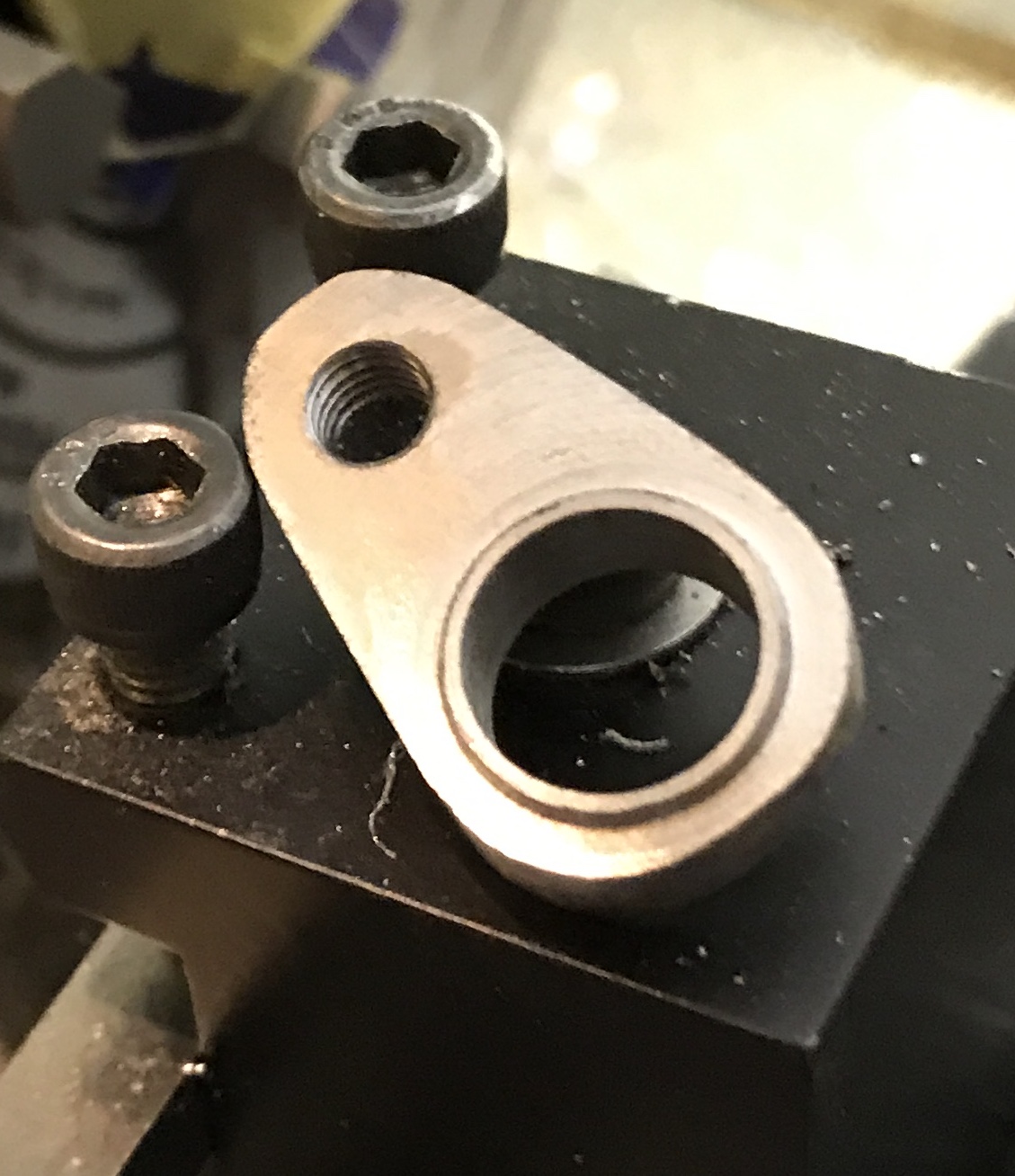
The gland was made from 3/8" hex brass stock. The 3" stock was held in the chuck and the end was faced and 3/8" was reduced to 0.25". This end was threaded 1/4-28 with a die in the tailstock die holder. The extra 1/8" was faced off and the end chamfered. The stock was drilled with a #42 drill to a depth of 0.40". It was parted off at 3/8" and deburred. It is a nice fit on the stuffing box, but highlighted the fact that the stuffing box is not aligned with the steam chest. Back to the propane torch to straighten it out. It certainly looks straight now. Ideally, I would have used a block of metal in the opening to hold both the bearing and stuffing box in place during soldering.
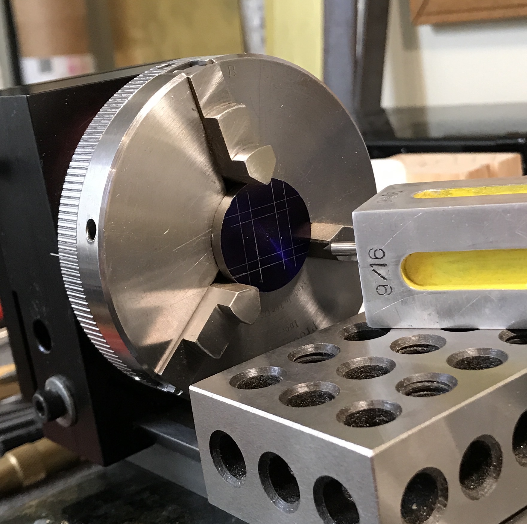
I can no longer remember my thoughts about the stainless required for the valve face. It is 1/16" X 1/2" X 1/2". I do not have any stainless in the box that is 1/16" thick. I do have a 1" stainless rod that does not seem to have any other use. Consequently, I will saw off a disk of this material and use the lathe to produce a 1/16" disk. I can also drill the center hole in the lathe after marking out the outline and rectangular hole. A 3/32" length was cut off with the hacksaw. Did not seem to be any more difficult to cut than mild steel. A collet was installed in the lathe spindle along with the three jaw chuck. A 1/4" rod was placed in the collet at such a length to hold the disk in a good position for facing. It was faced with a carbide tool in 0.005" increments very successfully.
Thinking the next steps through, I realized the disk cannot be thinned to 1/16" holding it in the chuck jaws. I will need to use an arbor. The arbor cannot have a nut covering the workpiece, so it will need to be an expanding arbor that can be sacrificed as needed. Alternatively, the desired thickness could be attained by milling and holding the parts of the disk that are waste. Like before the part was held in the chuck on the dividing head. The 1/2" square was laid out on center as was the inner 1/4" X 3/8" rectangle.
In order not to lose the layout lines for the inner rectangle during thinning the rectangular opening needs to be cut first. The center was marked. The part in the chuck on scrap was moved to the hex chuck holder. This was held in the vise. A line was oriented square with the use of a square held against the mill column. The spindle was aligned with the center and moved 3/32" off center. A hole was drilled, center drill followed by a #14 drill. The table was moved 3/16" back and a second hole was drilled. (Both holes protruded slightly beyond the lines!?) An hour of filing left a nice rectangular pocket (except for the drilling irregularities).
The aluminum rod seen below served well to shield my hand from the 1/8" diameter needle file shafts.
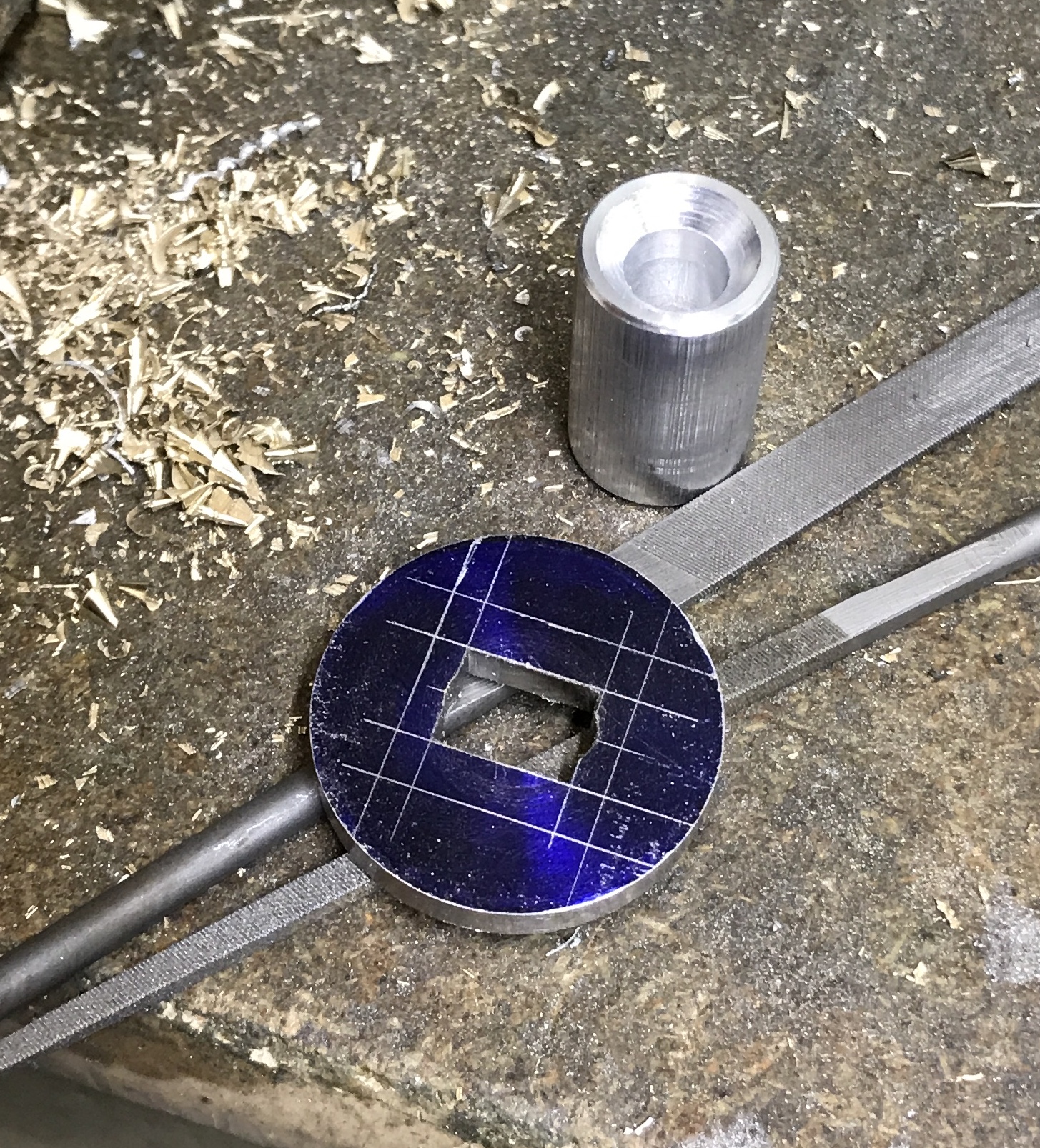
The central portion of the disk was thinned to 1/16" in the mill. It was clamped on 3/4" of bars on the angle plate to add height. A new 5/32" end mill was used in 0.010" passes to thin from one end to the other and just to the outside of the lines. It felt like I was milling aluminum. Most of the remaining waste was cut off with a hacksaw. The part was then filed to the line. A bit of sanding was all it took to complete the valve face. It is shown in the following photo along with the cleaned up steam chest and other parts.
The valve face was not finished after all. The next part is the valve back. A 9/16" length of 1/2 X 5/16" brass was cut with a hacksaw. The cut ends were milled so the part was 1/2" long. The next step was soldering the valve face to the valve back. The face was about 0.03" longer than 1/2" in both directions. In addition the opening was too narrow in the long direction. The sides were milled to correct dimensions and the opening was filed further. This filing got rid of the indentations from drilling. My layout lines were not correct for some reason. In any event the face is now properly sized and looks better than before. The two parts were arranged in the vise in the garage and solder was applied first to one end and then to the other. The valve was washed with soapy water, rinsed and dried. It was cleaned up with 600 grit sandpaper on all surfaces including the stainless steel valve face.
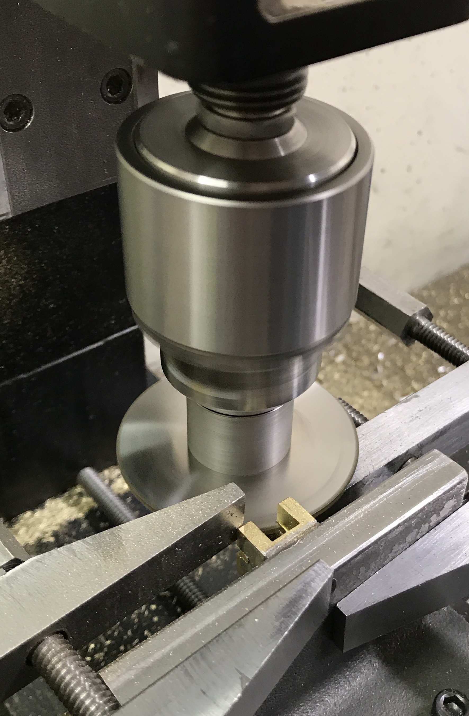
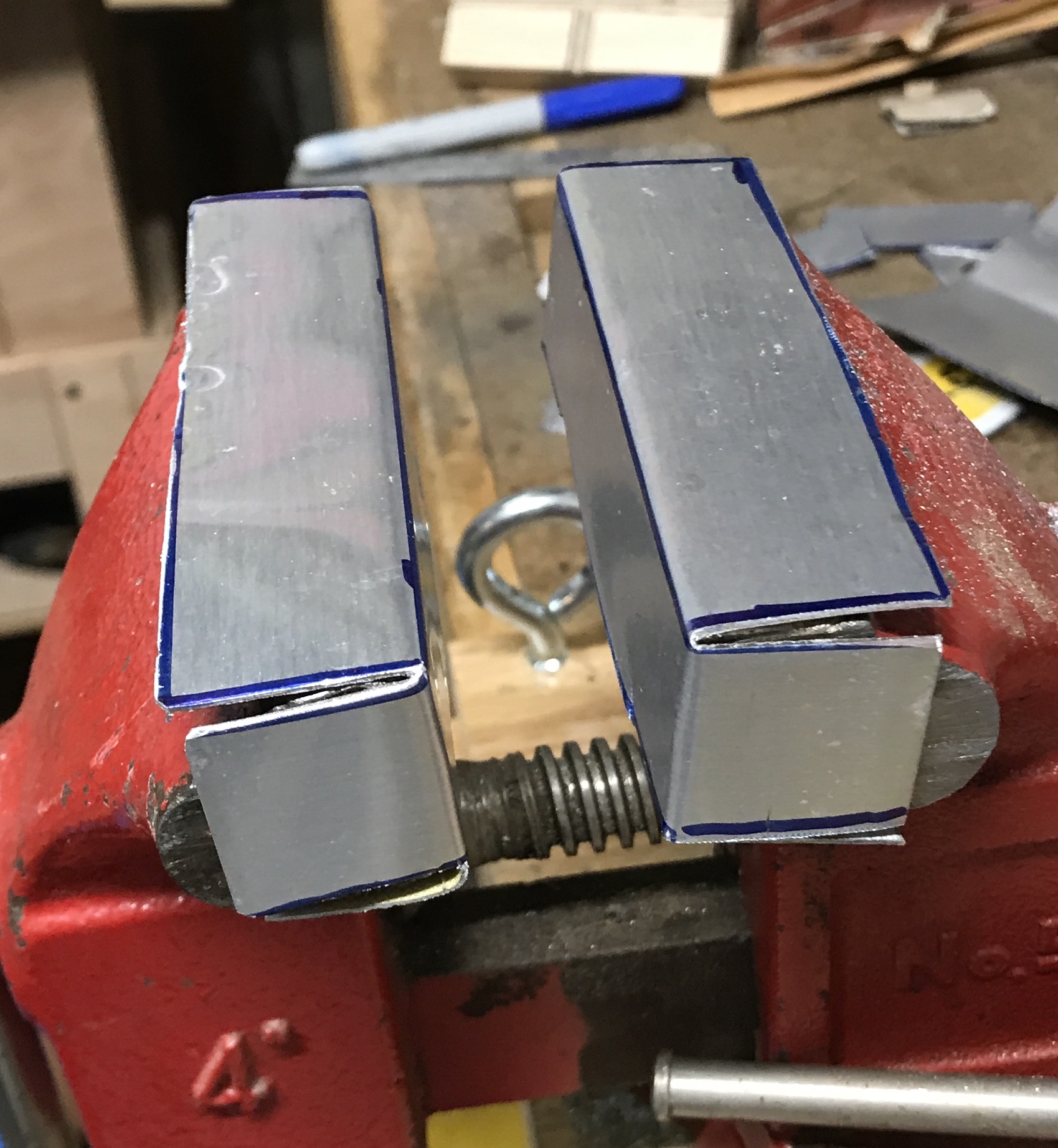
The wide slot was cut first in the soldered valve. In retrospect this should have been done second. A 5/32" end mill was used. The edge of the block was located and the spindle was moved to the center of the valve. A groove was cut 0.25" deep with a 0.020" depth of cut per pass. The groove was then widened to 0.25" with material removed on both sides of the groove. When this grooved block was set up to cut the narrow groove I could not use my 1/16" end mill. It is very short and I do not have an extension for the 1/4" collet. So the valve was set on end (groove running vertically) and clamped in the vise. This did not hold the part tightly. It was tight on the valve face, but not on the groove. It will have to be held with clamps on the angle plate and cut with a slitting saw.
Another idea briefly explored was using gage blocks to fill the groove and then hold it in the vise. The gage blocks were too long and stuck out too far for this to work. The picture below shows the final setup (two machinist's clamps on an angle plate). The valve was mounted vertically by using a machinist's square. The top of the valve was located with the bottom of the saw blade. The blade was lowered its thickness, 0.057", and then an additional 0.202". The slot was cut to depth in 0.005" passes. The depth was measured with a ruler. The blade was lowered an additional 0.039" to get the the correct, 0.096", width. These passes were cut in 0.010" increments. The second photo shows the completed valve after a little deburring.
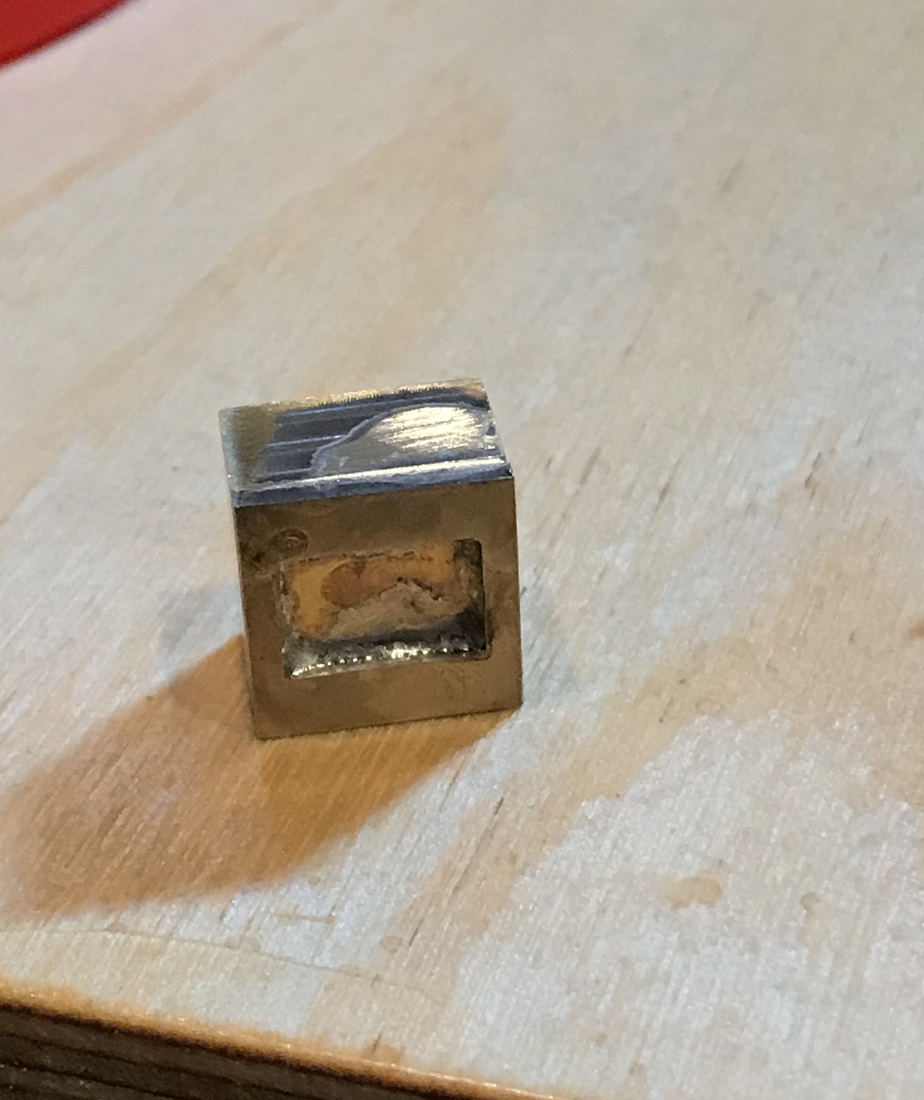
A small block of brass was cut and squared up to 0.25" X 0.25" X 0.50". A through hole was drilled through the center of one face with a #42 drill. A cross hole was drilled with a #43 drill and tapped 4-40. This is the valve nut. I decided not to make a stainless steel set screw and instead just use a standard 4-40 set screw. The 3/32" shaft was made next. I was unable to purchase 3/32" stainless rod, so I made it from 1/8" rod. A 3" length of rod was cut off and held in the chuck with about 1/4" sticking out. The end was faced using a carbide insert. The depth of cut was adjusted to remove 0.016" (0.032" diameter). The exposed 1/4" was reduced in one pass, another 1/4" was pulled out of the chuck and it was reduced. After multiple repetitions 2.5" of rod was reduced. The rod was parted off at 2.41". The gland was used to assess appropriate diameter. It did not fit over the rod. Measurement indicated the rod was 0.094" in diameter versus the desired 0.093". The rod was further reduced by filing and sanding. The sanding was finished with 1500 grit paper. The rod is now a nice sliding fit in the gland.
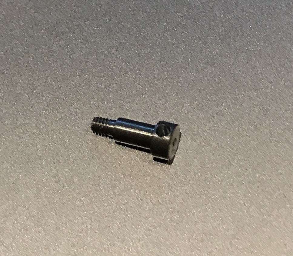
When the steam box parts were assembled it became clear that the stuffing box is still not properly aligned with the steam chest. It will need to be resoldered as soon as I can think of a way to ensure alignment. In the meantime I started the clevis and the pin. A 1/4" X 1/4" block of brass was cut to 1/2". It was squared up in the mill. A hole (#42 drill) was drilled in one small end. This will be soldered to the shaft. The pin was made from a 1" length of 3/16" steel rod. It was held in a collet in the lathe and faced. 0.34" was reduced to 0.125". 1/8" of the end was further reduced to 0.086" and threaded 2-56 with a die. The remaining 1/8" diameter section was polished with crocus cloth. It was parted off at a total length of 0.41". It was transfered to the vise on the mill. The spindle was centered over the large end and 1/16" in from the end. It was dimpled with a #0 center drill and then drilled 3/32" deep with a #52 drill for a tommy bar. The photo below shows the completed pin.
Another attempt was made to reorient the stuffing box perpendicular to the steam chest. A length of 1/4" threaded rod was screwed into the stuffing box. The joint was heated until the solder melted. The rod was adjusted with some difficulty so it was vertical above the steam chest held in the vise. When the parts cooled it was clear that the stuffing box was still not perpendicular. If the rod is screwed in tightly it is not aligned with the stuffing box! If screwed in loosely there is too much play for any chance of success. The only alternative I have come up with is removing the old stuffing box, solder in a long brass rod, cut it to length, and machine it in place. The steam chest is held nicely by the valve stem in a collet.
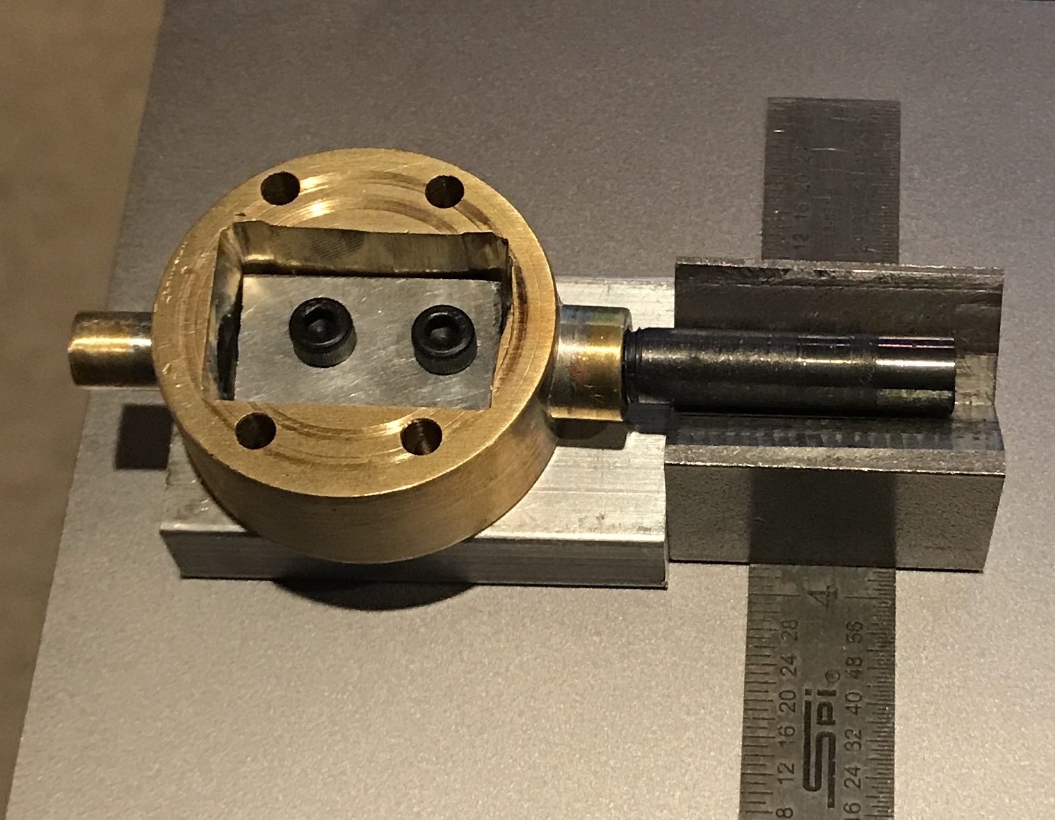
I am resisting making a second stuffing box. I was able to thread the box a little deeper so the alignment shaft fit much better. Unfortunately, melting the solder and aligning the shaft still did not work. So yet another idea will be tried. After taking some measurements and a little geometry I will use a small jig and vee block. The jig is essentially a stand to raise the steam chest to a level such that the shaft if aligned correctly will fit in the vee and align it in two directions. The jig also has a screwed on block of aluminum that is a decent fit in the steam chest opening. The photo below shows the general idea. The vee block will be clamped to the jig when in use.
The alignment jig did not perform any better than attempting to align the shaft by trial and error. The stuffing box was removed. I plan to make a new stuffing box and drill it in place. Well it worked, but ... Turns out the valve stem bearing was also poorly aligned with the steam chest. So now the valve stem travels nicely, but it travels out of square with the steam chest. This may not matter as it is connected via a joint to the rest of the mechanism. We can only hope!
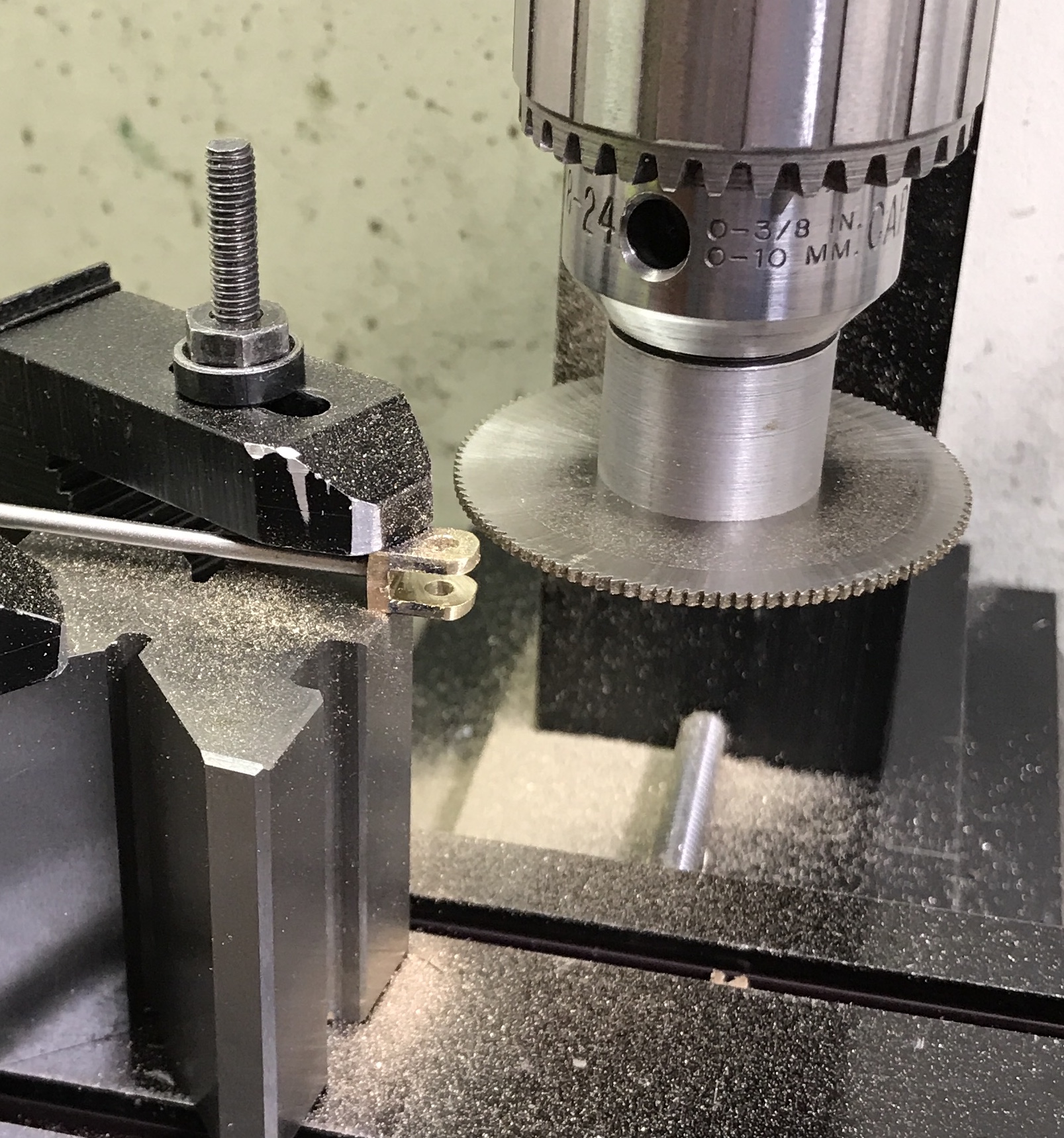
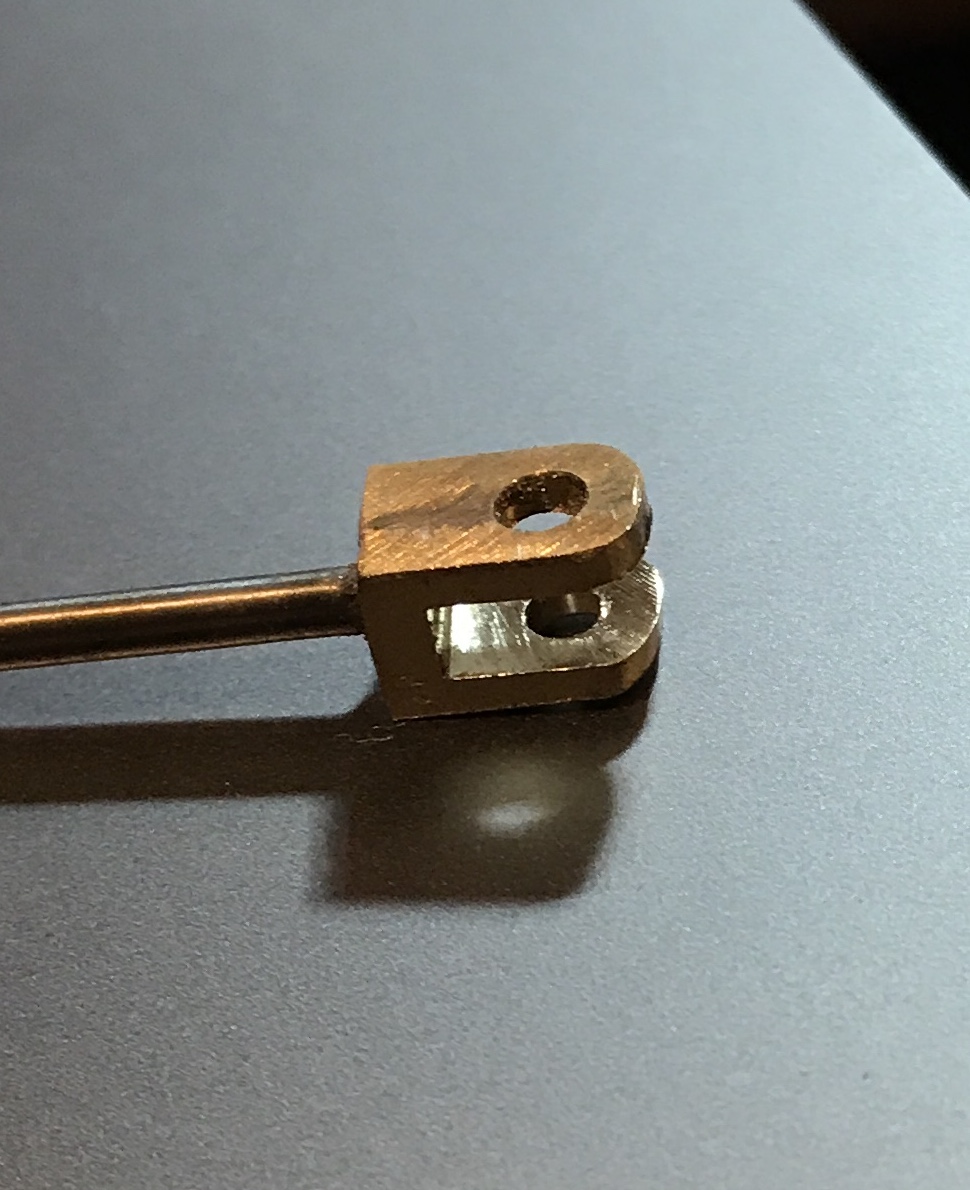
The clevis was finished. The hole and end radius were marked out. The end was milled close to the radius line and then the radius was finished with a small file. The hole was drilled and reamed 0.125". The clevis was set up on the side of a vee block and clamped with a strap clamp. The 0.057" slitting saw was used to make a cut 0.30" deep leaving about 0.09" uncut. The saw was then lowered its width and a second cut was made to the same depth. After deburring and sanding with 600 grit paper the clevis is shown in the second picture below after the sawing setup photo.
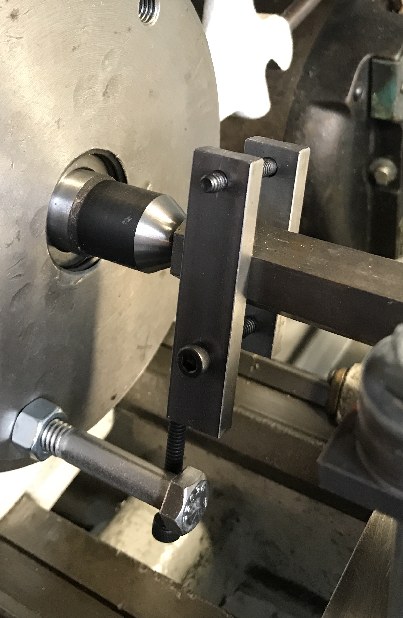
Spent the morning setting up the South Bend lathe for making the cylinder. A 2.5" length of 1.25" bronze round was cut with the hacksaw after scribing a line around the rod. Sawing down along the scribed line on occasion gave a very square cutoff. The lathe was setup with the cross slide plate. Mounting the bronze rod on a vee block put the center of the rod 1/16" below the tailstock center. Setting the vee block on some 1/16" thick brass scraps aligned the tailstock center nicely with the center of the workpiece. The plate was squared with the lathe and the vee block was squared relative to the plate. Two holes were drilled in a 1/4" X 3/4" bar of steel to match the holes in the plate. They were drilled 25/64" diameter. Two long screws were found to clamp this bar to the top of the bronze. The screws were too long, but a stack of washers for each made them work. After replacing the 3-jaw chuck with the faceplate I realized that I do not have a lathe dog that is large enough for the 3/4" hex used in the between centers boring bar.
Found steel stock that is 1/4" X 1/2". Two pieces were cut off, one at 2 5/16" and one 1/2" longer. The ends were chamfered. In the short piece a hole was drilled and tapped 10-24 1/4" from the end. The other end was drilled for a through hole with a #10 drill. The longer piece was drilled for a through hole 1/4" from one end. Aligned with the second hole on the shorter piece it was drilled and tapped. All holes were chamfered. I will need to take this out to the lathe to determine how the longer end needs to be modified so it can be driven by the face plate.
The holes in the face plate are 2.5" from center. The end of the long leg of the dog was drilled and tapped for a 10-24 screw. After installing the dog was assembled on the between centers boring bar. The short boring tool was sharpened on an Arkansas stone and inserted into the boring bar. It was set so the cutting tip was 5/8" from the center of the bar, since this is the radius of the bronze stock. The lathe dog and the setup are shown in the following photos. The 1/16" brass plates beneath the vee block are not visible in the photos, but the gap between the vee block and the base plate is clearly shown.
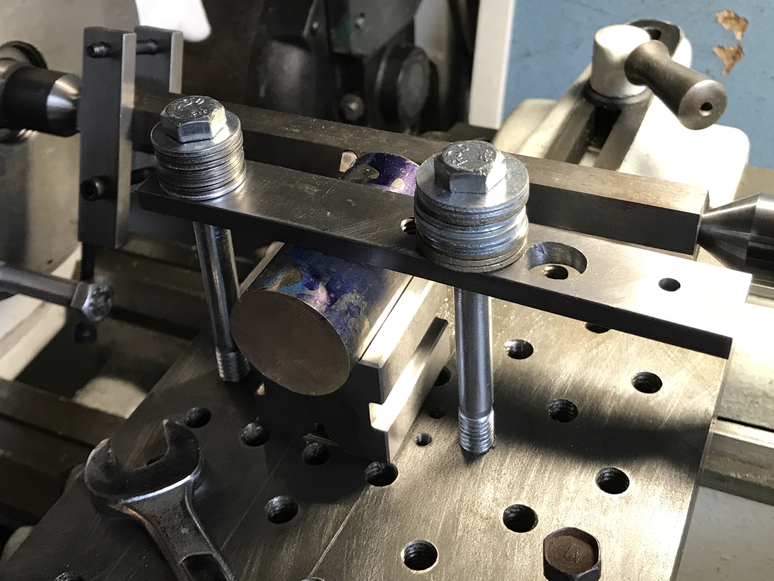
A trial run was made by hand cranking the carriage. Everything proceeded well. I am not sure what speed to run the lathe. I guess somewhere between 500 & 1000 rpm. I will also need to experiment with auto feed to find a slow, but effective speed. Since I can probably only remove a few thousandths per pass, the autofeed becomes a necessity. The setup gets within 1/4" of the driving screw as the cut is completed. Autofeed will need to be carefully monitored to avoid crashing the lathe.The cylinder can probably be shifted 1/2" to the left to provide a 3/4" margin of error.
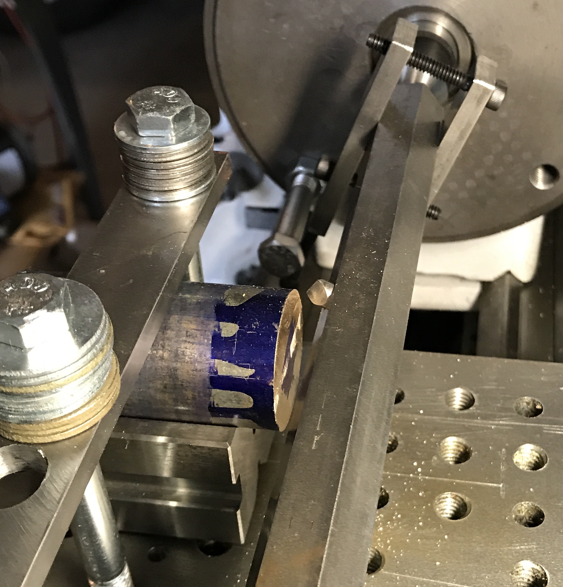
I watched about half of the videos in Mr. Pete's series on the South Bend lathe. A section covered the automatic feed. It was quite informative. So I gave it a shot this afternoon. The Forward/Reverse lever on the left side of the lathe was set in the top position (carriage moves to the left and cross slide to the back). The left lever selector on the gear box was set on C (rotate the chuck if it does not engage). The right lever selector was set in the sixth hole from the left (rotate the feed screw if it does not engage). This is the setting for 48 TPI or 0.0071" per revolution of the spindle. The tool was touched off and the cross slide was advanced 0.005". The feed selector lever was moved to the top hole (carriage movement). The clutch was engaged with a clockwise turn. The tool moved at a slow but effective rate across the face of the cylinder. A block of wood was placed in front of the cylinder to catch chips and keep them out of the holes in the plate. The clutch was disengaged when the cutting tool moved past the cylinder. This left the plate about 1/8" from the dog. After about 10 passes there is a noticeable depression in the end of the cylinder as seen below. Cutting was stopped. The cylinder needs to be moved left and the lathe needs to be oiled before continuing. A successful experiment!
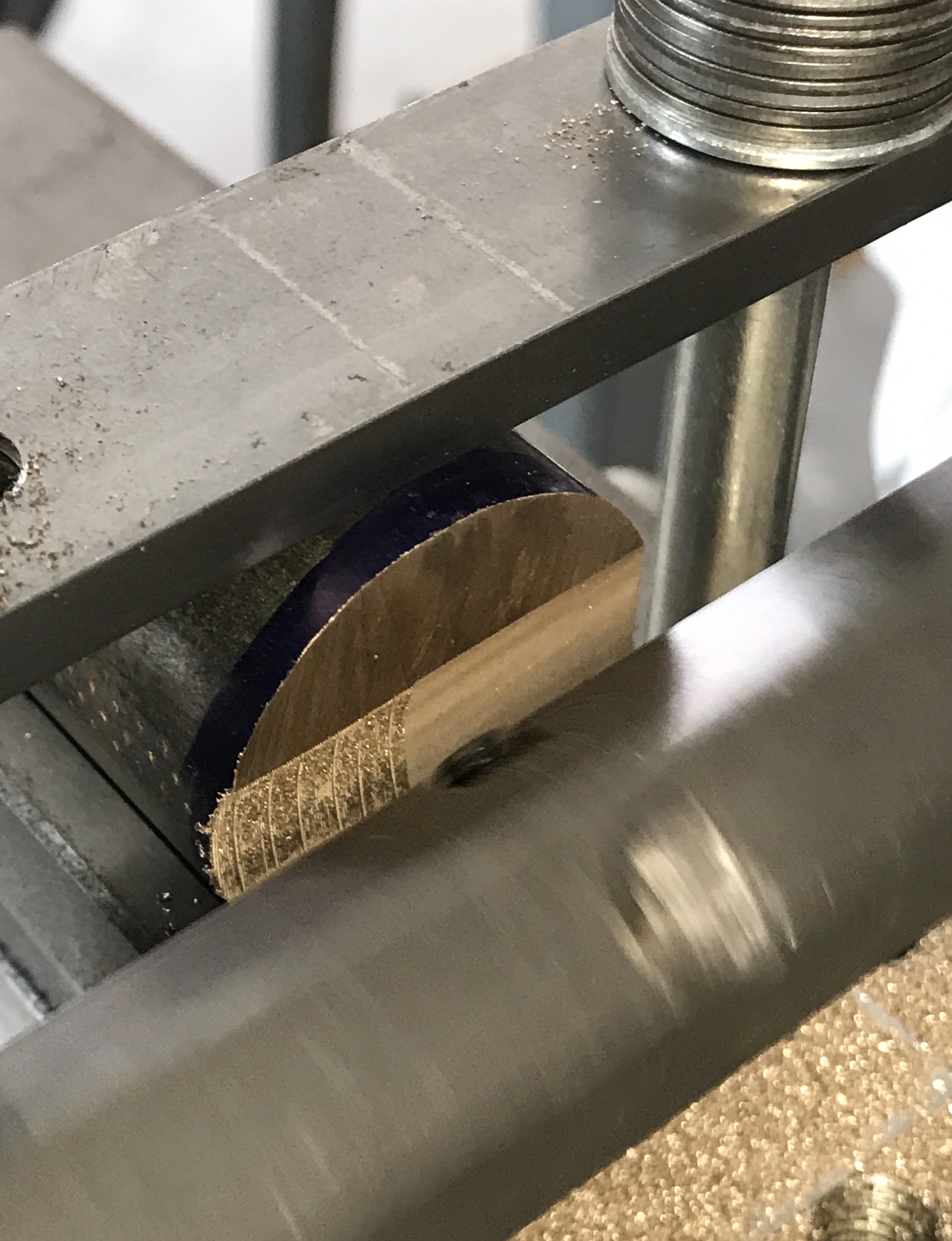
The part was moved about 1/2" to the left and squared before tightening the strap clamp. The lathe was oiled in all places except the ways and the back gears. The part was then cut about half way with many passes. The lathe is still remarkably quiet and the work was pretty effortless. Had to stop to go for a walk at Ft. Harrison State Park. The movie below shows the lathe in action.
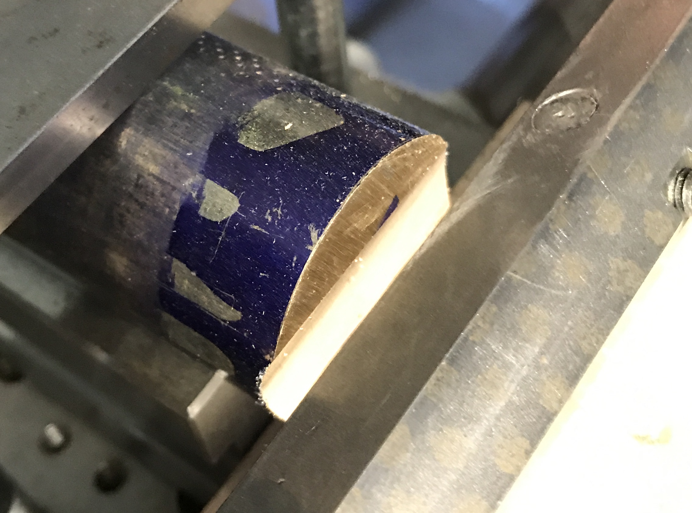
The half bore was completed this morning in the 50° garage. A check fit part way through showed a poor fit and asymmetrical cut. The bottom was about 1/16" thicker than the top. The bronze is not 1.25", but 1.28". A 1/32" shim was placed below the vee block beneath the 1/16" shim already there. The tool was set so it was 1.015" from the back side of the boring bar. This gave it a cut radius of 0.64". The cut was completed. The photo below shows a reasonable but not perfect fit. The bore seems to be a little deeper than it is wide.
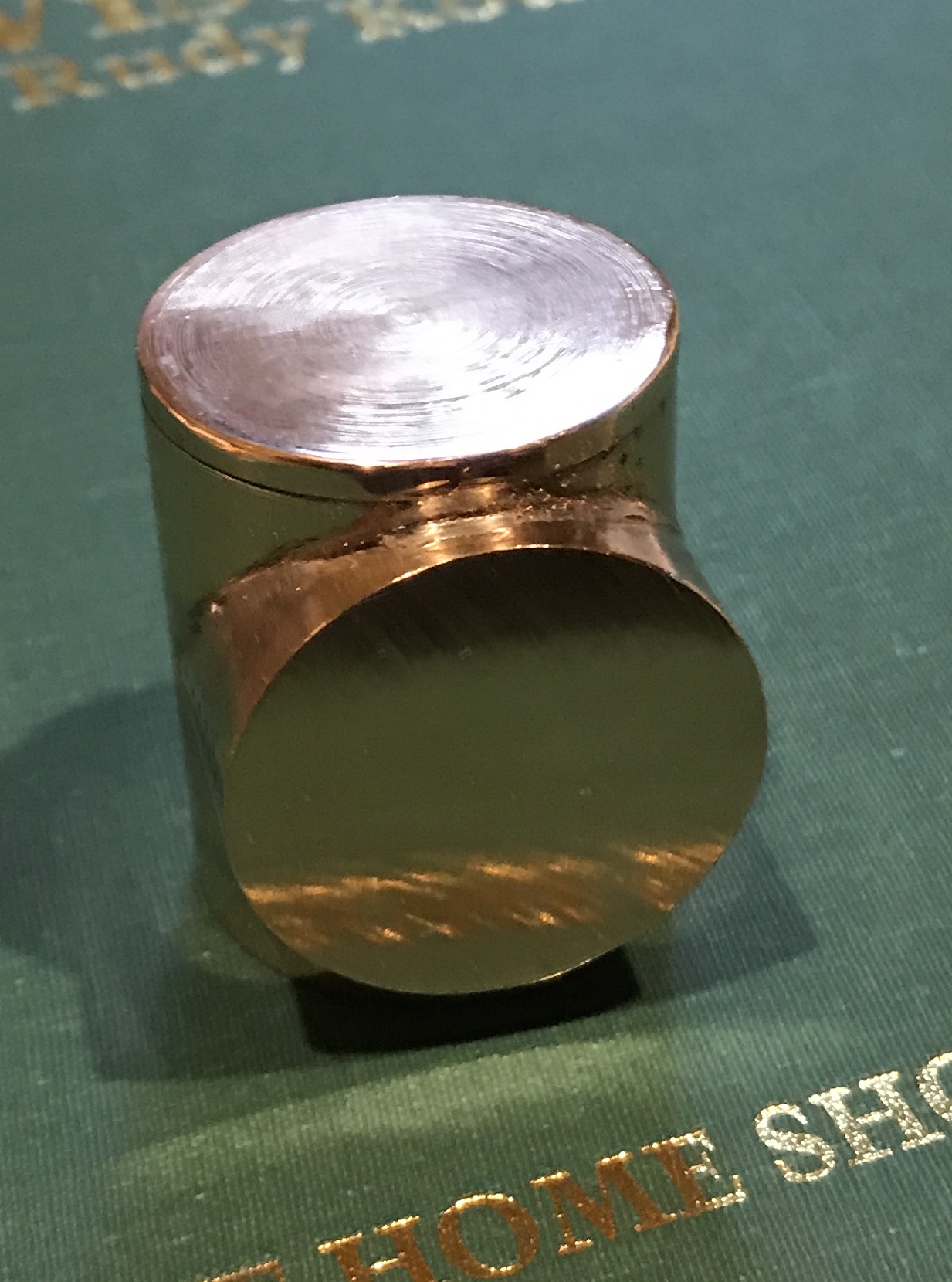
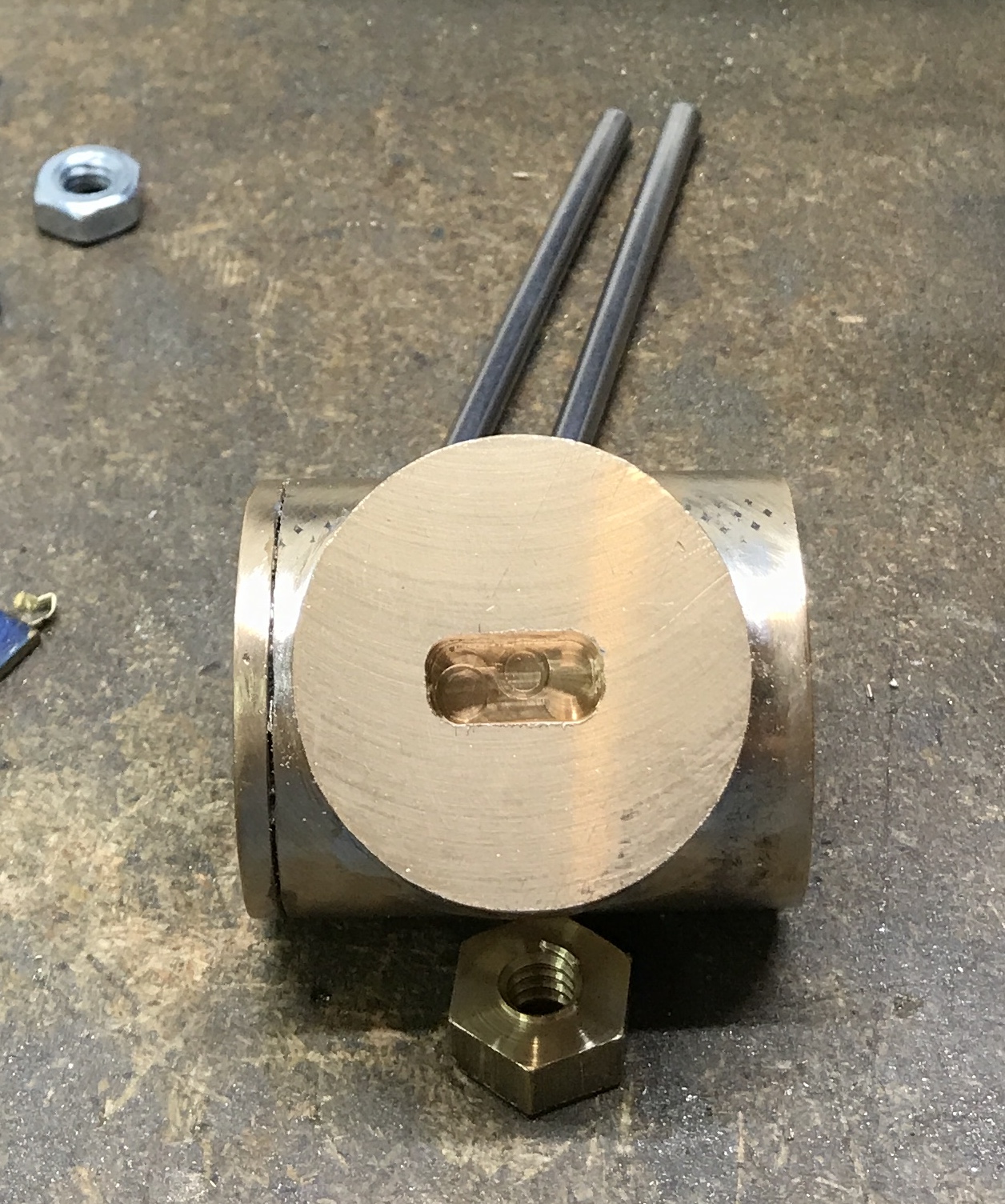
Used a file to widen the half bore giving a better fit around the shaft. Cut off the part at 1 9/16"!!! Needed to be 1 11/16"!!! (This was not an April Fool's day joke.) Now what? You can cut it off, but you can't put it back on. Time to test the truth of that old saw. I will make a disk that is 3/16" thick and solder it onto the rod prior to soldering on the half bore. The disk was cut off the scrap piece. It was faced on both sides. The corners were lightly deburred with a file. It is 0.215-0.220" thick.
The plate was aligned with the body of the cylinder and soldered in place. Two strips of solder were 'melted in' from opposite sides. (The propane cylinder finally ran out. The cylinder that I purchased four years ago when I thought the first was low was used to finish the joint.) After cooling the bronze cylinder was aligned (± 0.002") in the three jaw chuck in the Sherline lathe. It was faced. This face was then placed against the chuck body and the opposite face was faced. The body of the cylinder was sanded. I left some marks on the cylinder sides. I didn't want to remove too much material sanding and I like it looking as if it were old and a little worn. The length was measured. An additional 0.100" was faced off of the soldered addition.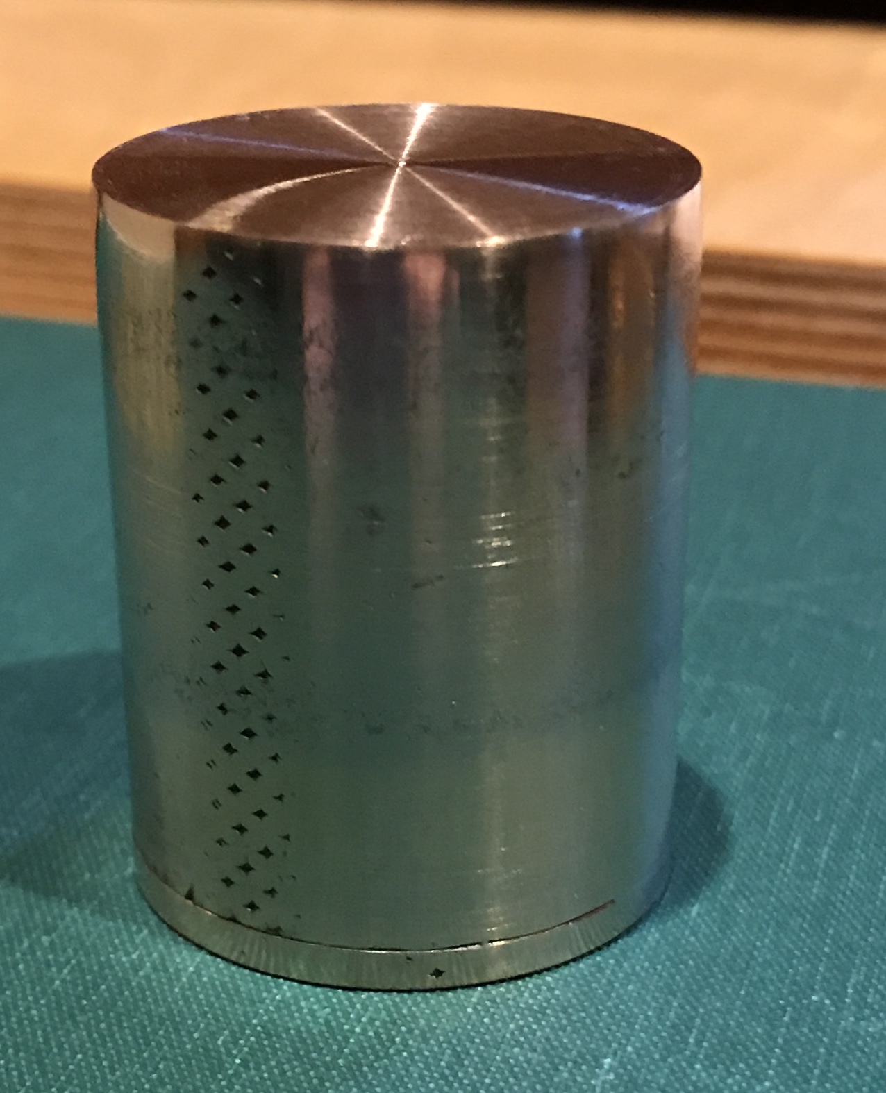
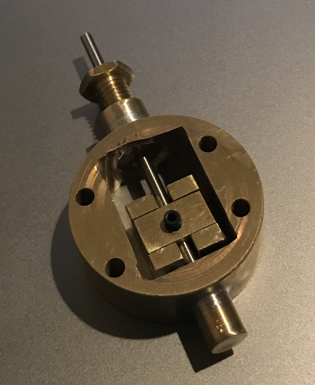
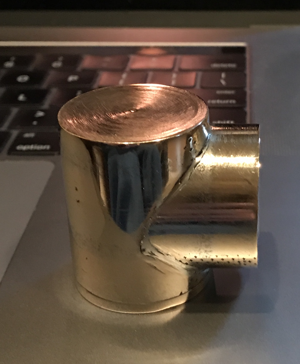
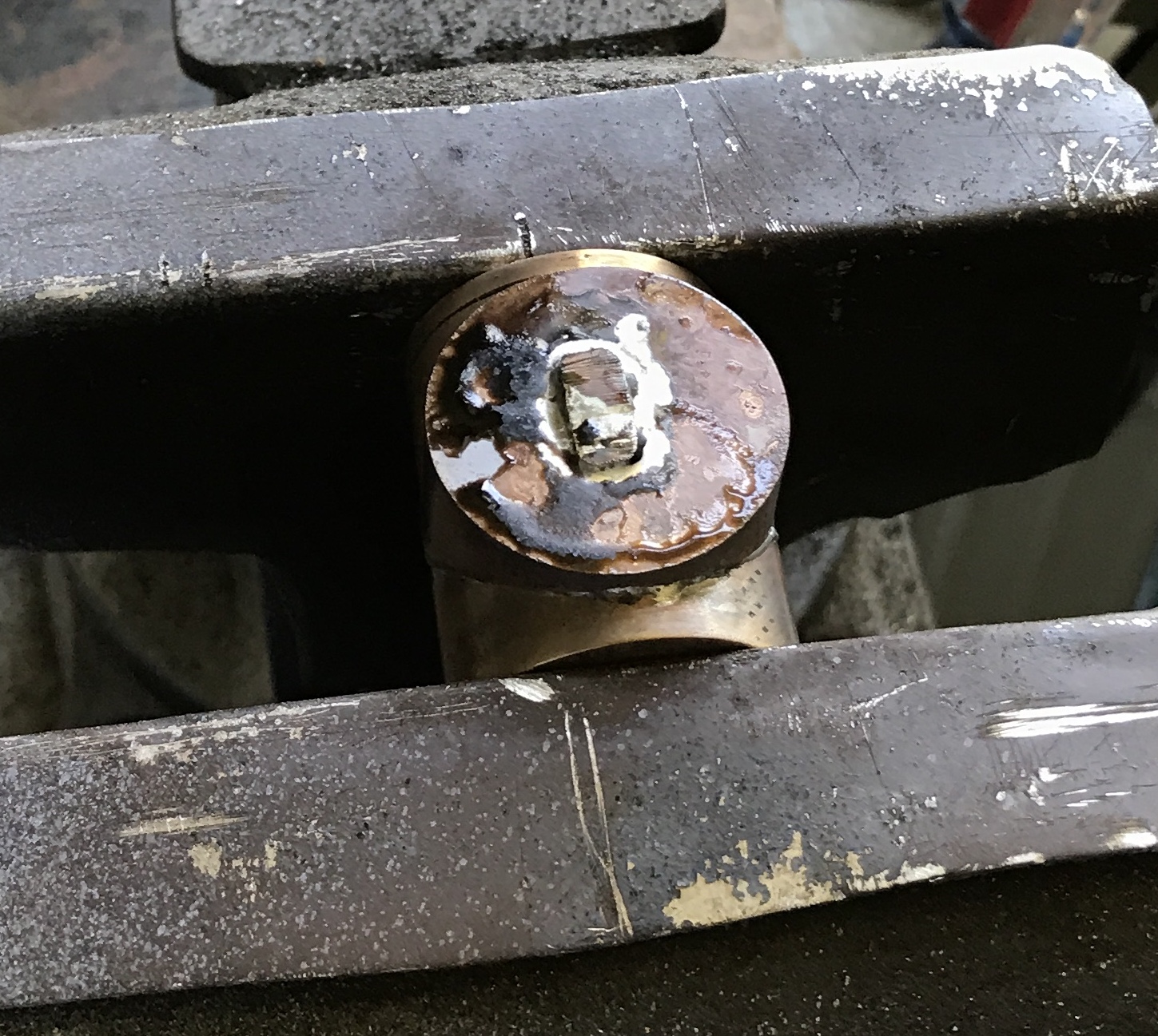
This morning was spent soldering the port face to the cylinder. Some time was spent filing the curve of the port face to better match the cylinder. This helped somewhat. The port face was clamped to the cylinder in the garage vise. It was clamped so each side was about 3/16" from the end of the cylinder. The joint was fluxed first. A length of solder was placed on the joint and the joint heated with the torch. This was done for both sides and then repeated as the joint absorbed a lot of solder. After cooling excess solder was removed with needle files. The entire cylinder assembly was sanded with 150, 320, & 600 grit sandpaper. The cylinder was then polished. The picture below shows the completed cylinder. Not great, but acceptable.
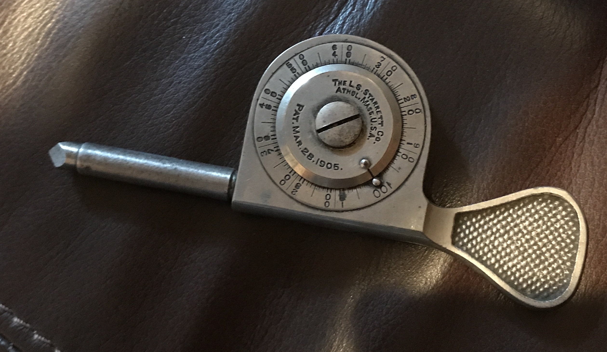
Received a new tool this afternoon. I purchased a Starrett revolution counter on eBay for $8.50 plus $4 shipping. One revolution of the wheel is one hundred turns of the spindle. I will try it out when I break down the current setup.
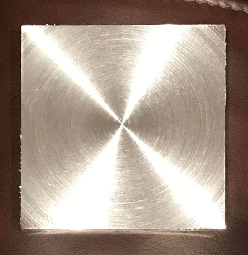
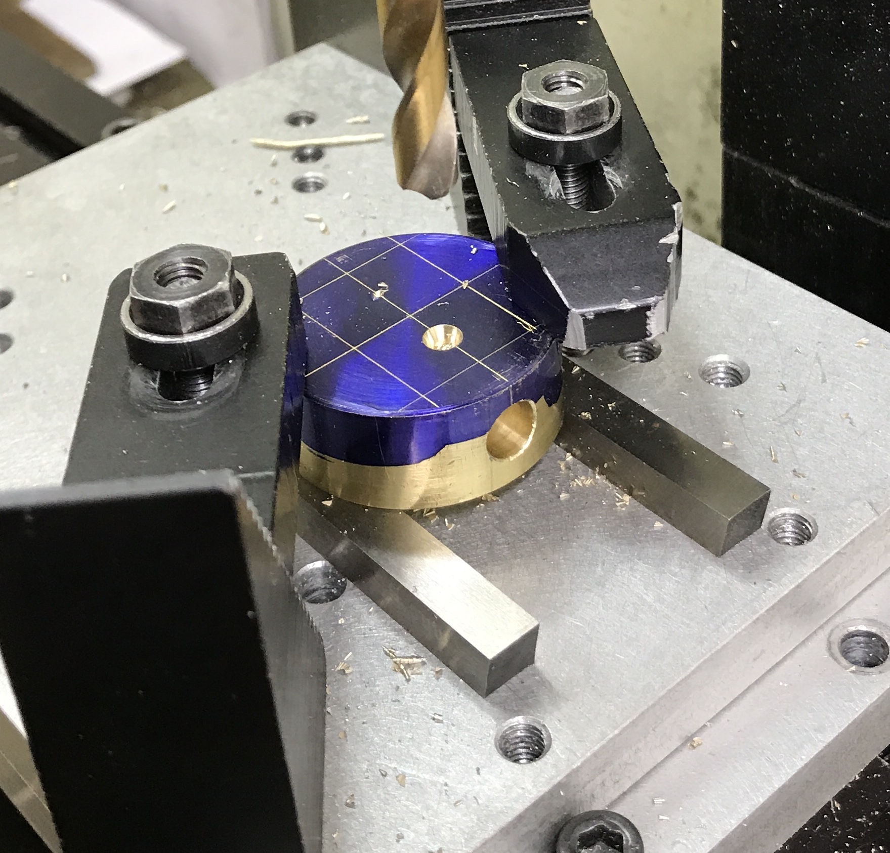
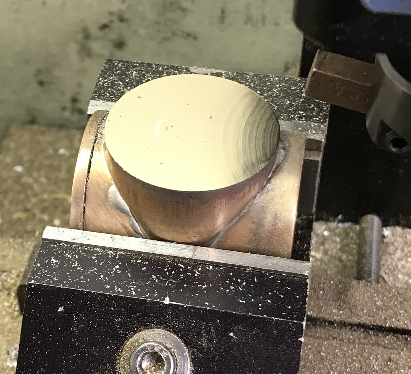
The port face need to be thinned. A Sharpie mark was made all around the face at 1/4". A 1/4" disk was removed with a hacksaw. The part was held in the milling vise and the sides of the port face were aligned square with the table via a vee block and a square. 3/64" was removed with a carbide insert fly cutter. This left a beautiful finish and a nasty burr. The burr was removed with a small file. The picture below highlights the mirror-like finish.
The two exhaust ports were drilled in the cylinder. The port face was set flat on the bottom of the vise. The center of the 1.284" cylinder was located with the edge finder. One end was then located and the spindle moved to 0.080" in from the end face. A hole was center drilled, drilled with a #43 drill, and tapped 4-40 to 3/16" deep. The opposite end was then located with the edge finder and a tapped hole was made: again 0.080" from the end.
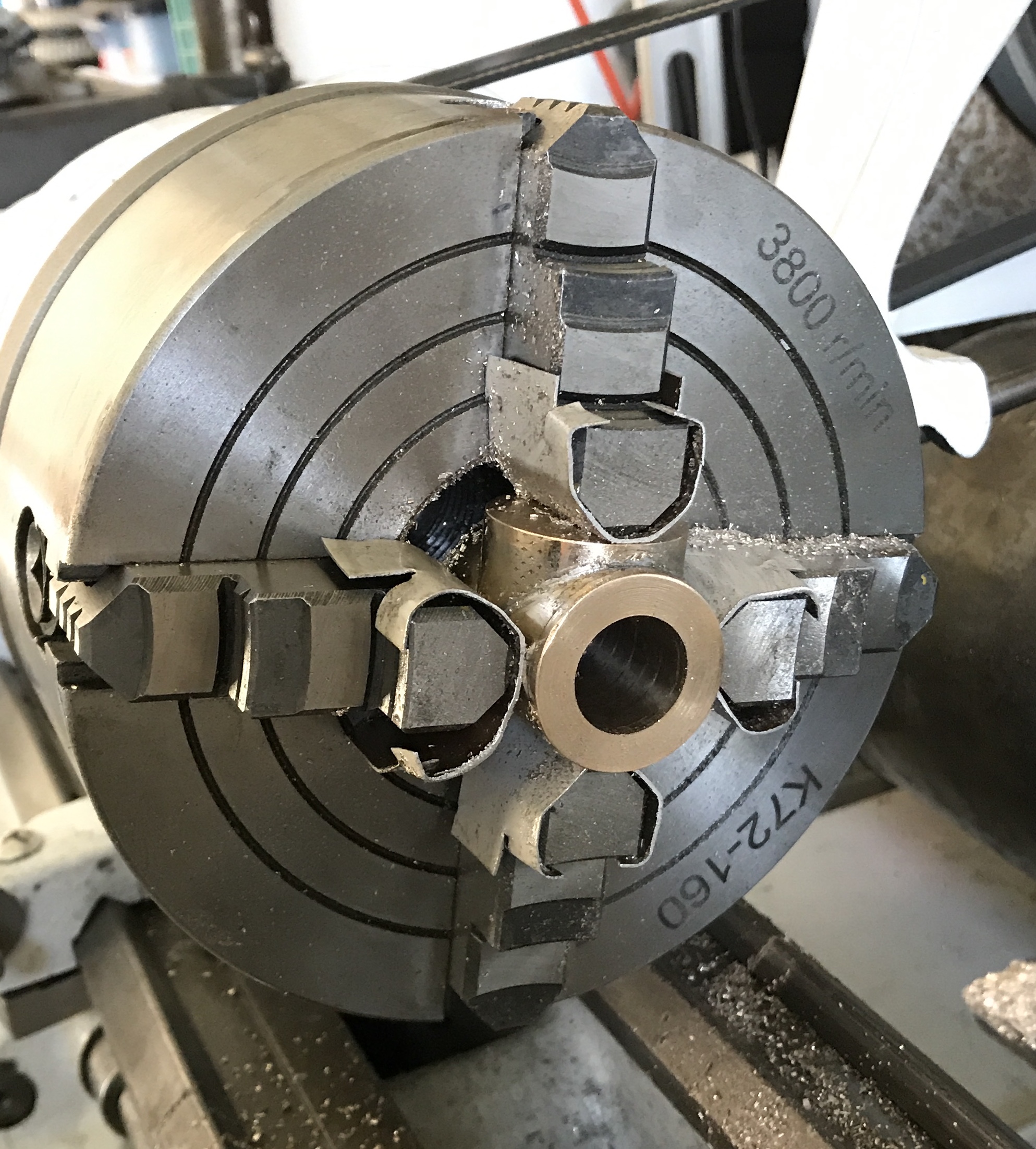
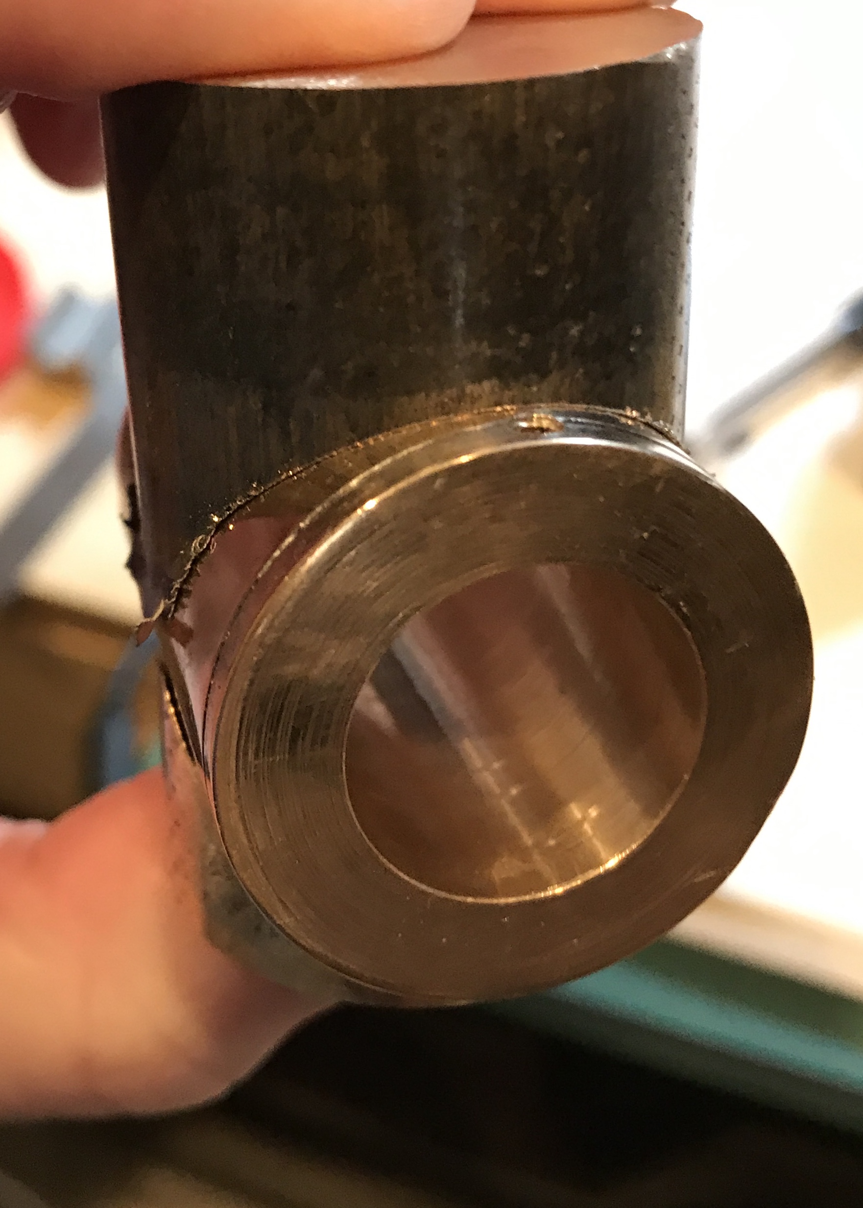
The cylinder bore was tackled next. As opposed to holding a still part as was done earlier, the cylinder was held in the four jaw chuck with aluminum soft jaws. It was indicated in to within 0.001". The cylinder was center drilled and drilled through with a 1/4" drill. The hole was opened up in 1/16" increments to 11/16". A boring bar was used to open the cylinder the rest of the way. Automatic feed (0,007" per revolution) was utilized. The edges of the opening were deburred. The final diameter was 0.759-0.761". The piston will need to be made slightly oversized to fit. The photo below shows the setup and finished bore.
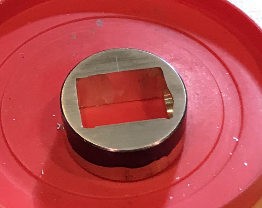
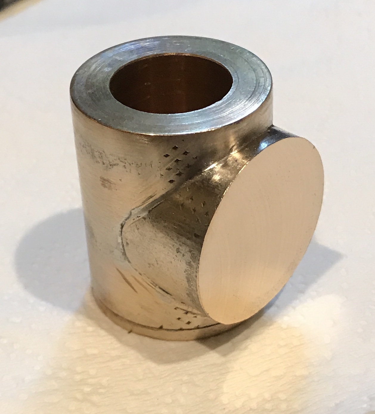
Decided to remake the port. It was a poor fit and potentially not even sealed. The setup from before was repeated. The cutting tool was very carefully set at 1.015" (desired radius, 0.640", plus the bar's radius, 0.375"). The finish was not great, so after cutting 0.100" deep the tip of the tool was slightly rounded and resharpened with a diamond hone. This gave a very nice finish as seen below. The fit was checked at 0.1" and 0.4". Perfect fit both times. After an additional 0.200 the fit was not as good. A quick check showed that the cutting tool had shifted. It was reset and the good fit returned. A check with a hole gauge against a ruler held over the end indicated the current depth is 0.523". The part will need to be moved as the tool is getting close to the vee block. Slow and careful may win this race. The final depth was measured at 0.635". The picture below of the yet to be deburred part shows the excellent fit on the cylinder.
The port was deburred. The cylinder and old port face were separated by heating with the blow torch. Excess solder was removed with a file. The new and improved port was soldered on. A significant amount of solder needed to be removed by filing and sanding. So after making some aluminum soft jaws from an old license plate (found when we cleaned the garage), the part was clamped up. It was filed and sanded with 220 grit sandpaper. The face was then thinned as above to 1/8". The photo below shows the improved cylinder.
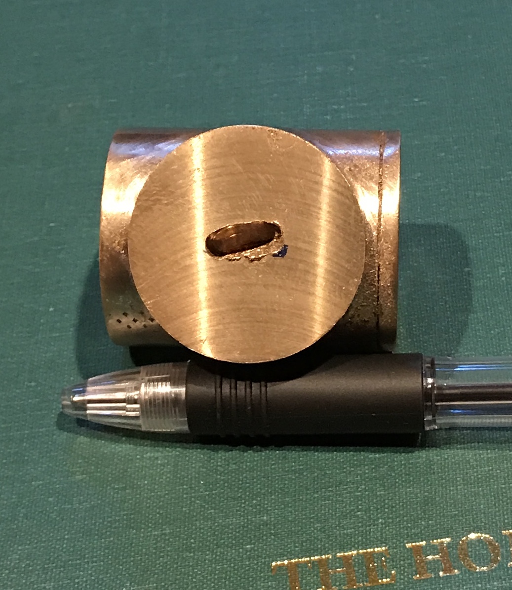
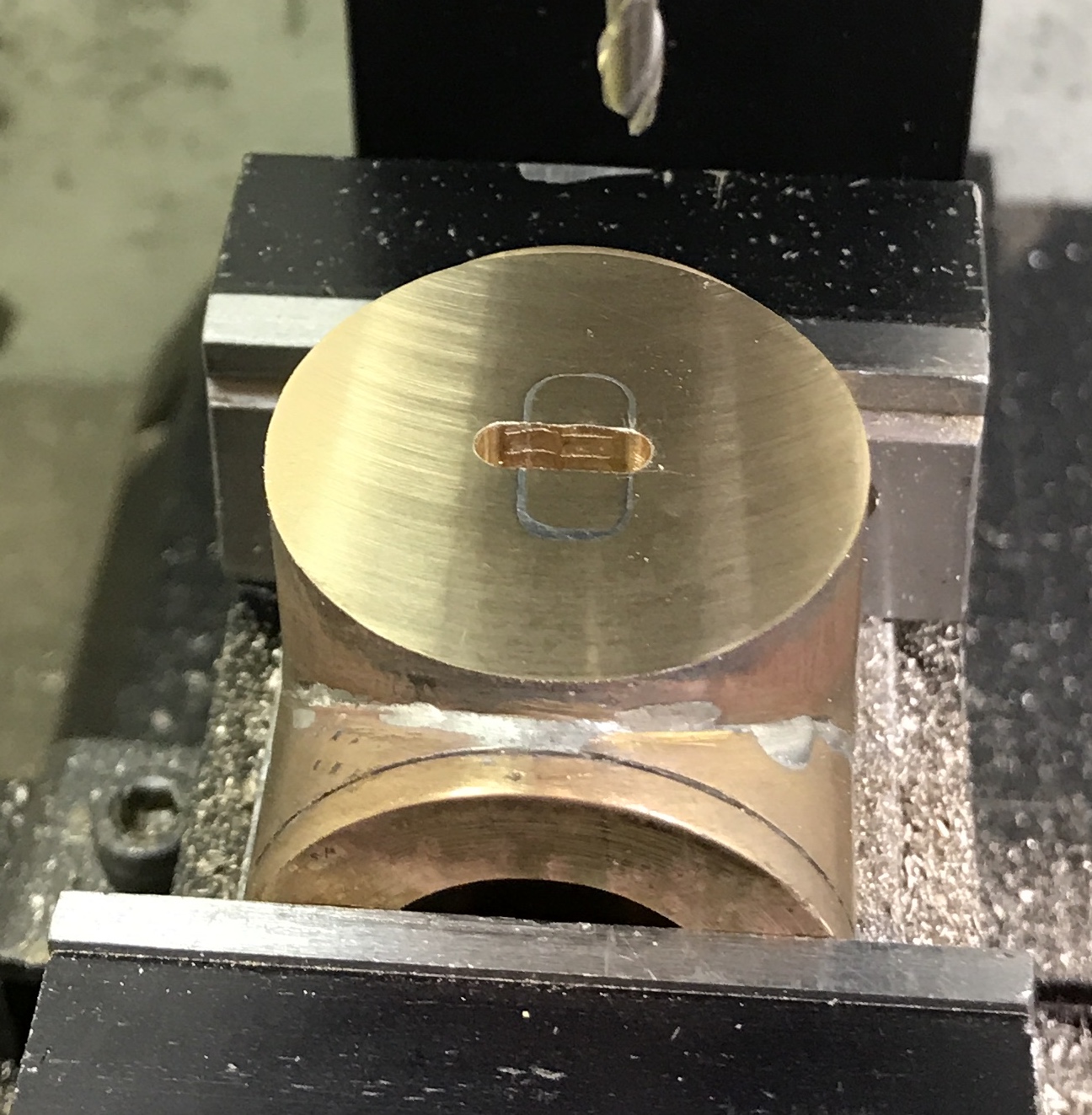
Two holes were drilled in the back of the cylinder through to the bored opening. They were drilled 0.080" from the ends opposite the port face. After drilling them through with a #43 drill they were tapped 3/16" deep with a 4-40 tap. Milling the slots for the steam and exhaust ports was next. The port face was squared up in the vise. The edges were located and the 1/8" end mill was moved into position. It was lowered 0.020" and the 3/8" slot was milled. This was repeated to a depth of 0.31". There were a lot of chips built up in the slot. This resulted in a horrendous slotting outcome. The picture shows the result: angled and misshapen. I was so disappointed with this result that it has been three weeks since the mistake was made before I wrote it up. I didn't even notice the other major mistake until I milled the new slot. The bad slot is oriented incorrectly!!
I need to plug the slot and recut it. I will first open the damaged slot so it is even and square. Then a plug will be made to fit and soldered in. The new slot was cut with a 5/32" end mill. This slot is 0.225" X 0.480".
A plug was cut from a scrap of bronze. It was filed until it fit. The plug was then put in the slot, treated with flux, and soldered in place. The photo below shows the plug soldered into the slot. The part was washed with soap and water. Most of the excess plug was removed with a file. The rest was fly cut after careful squaring and tight clamping. The second photo shows the cleaned surface. The soldered joint can be seen if the photo is blown up.
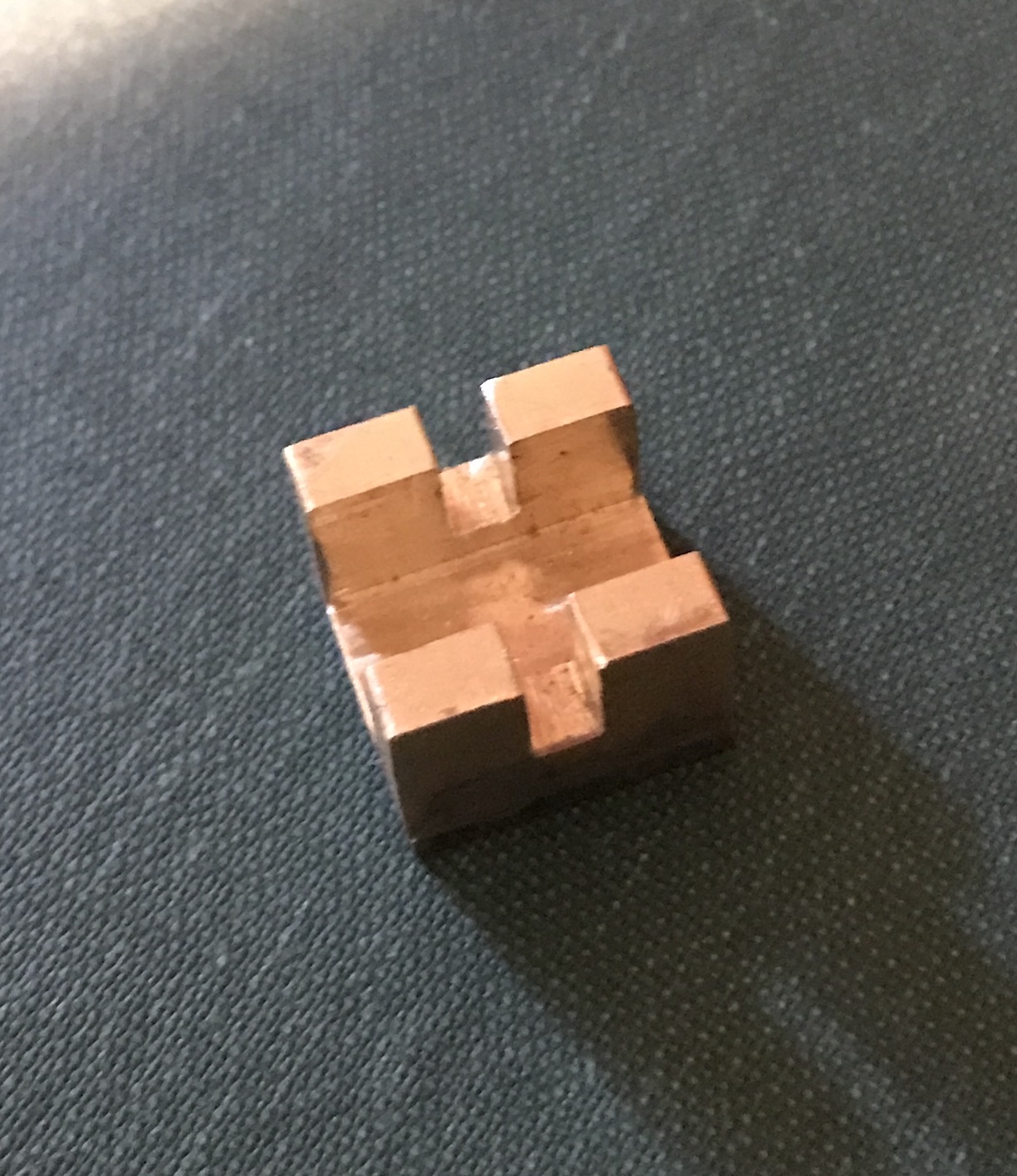
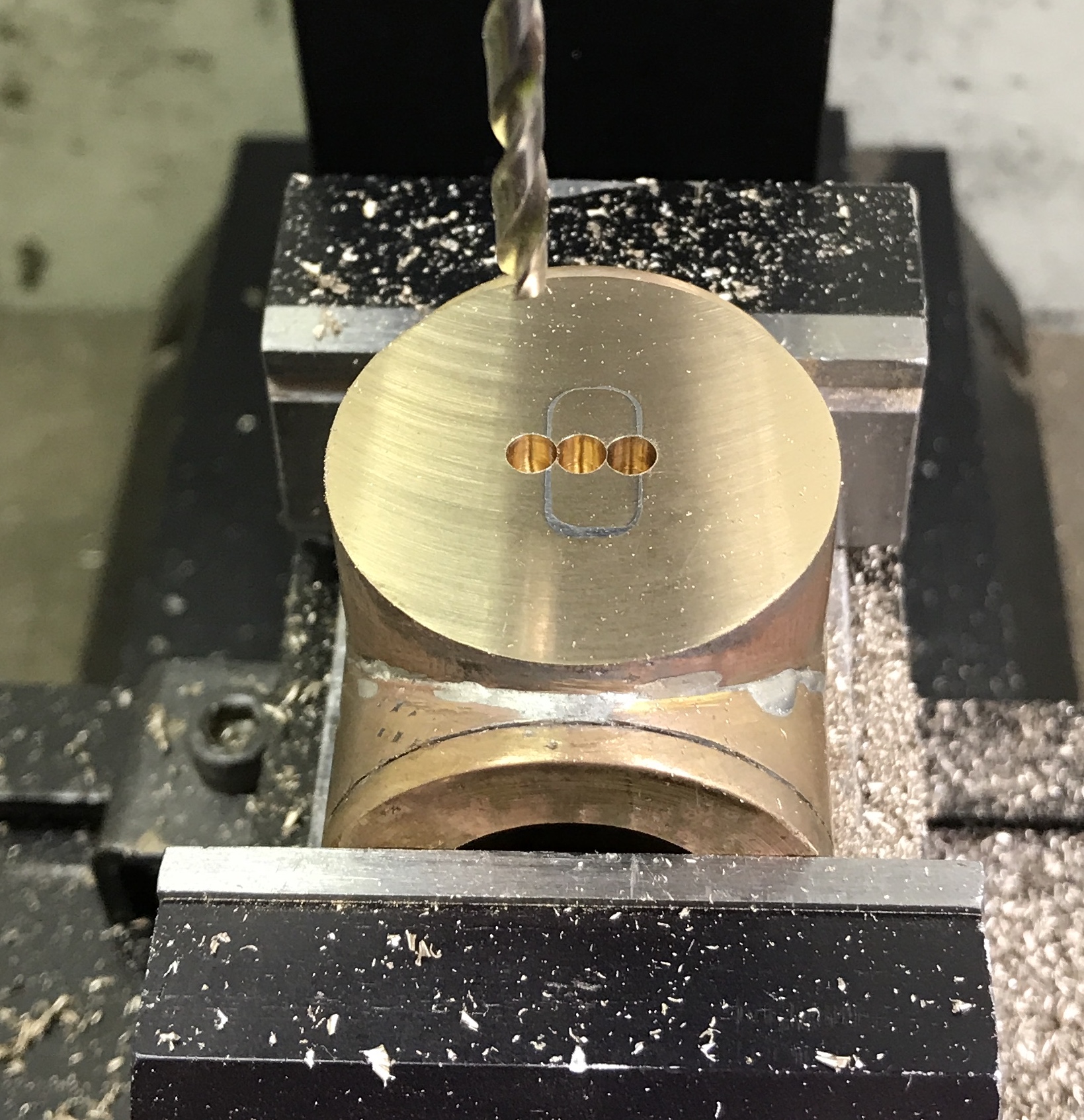
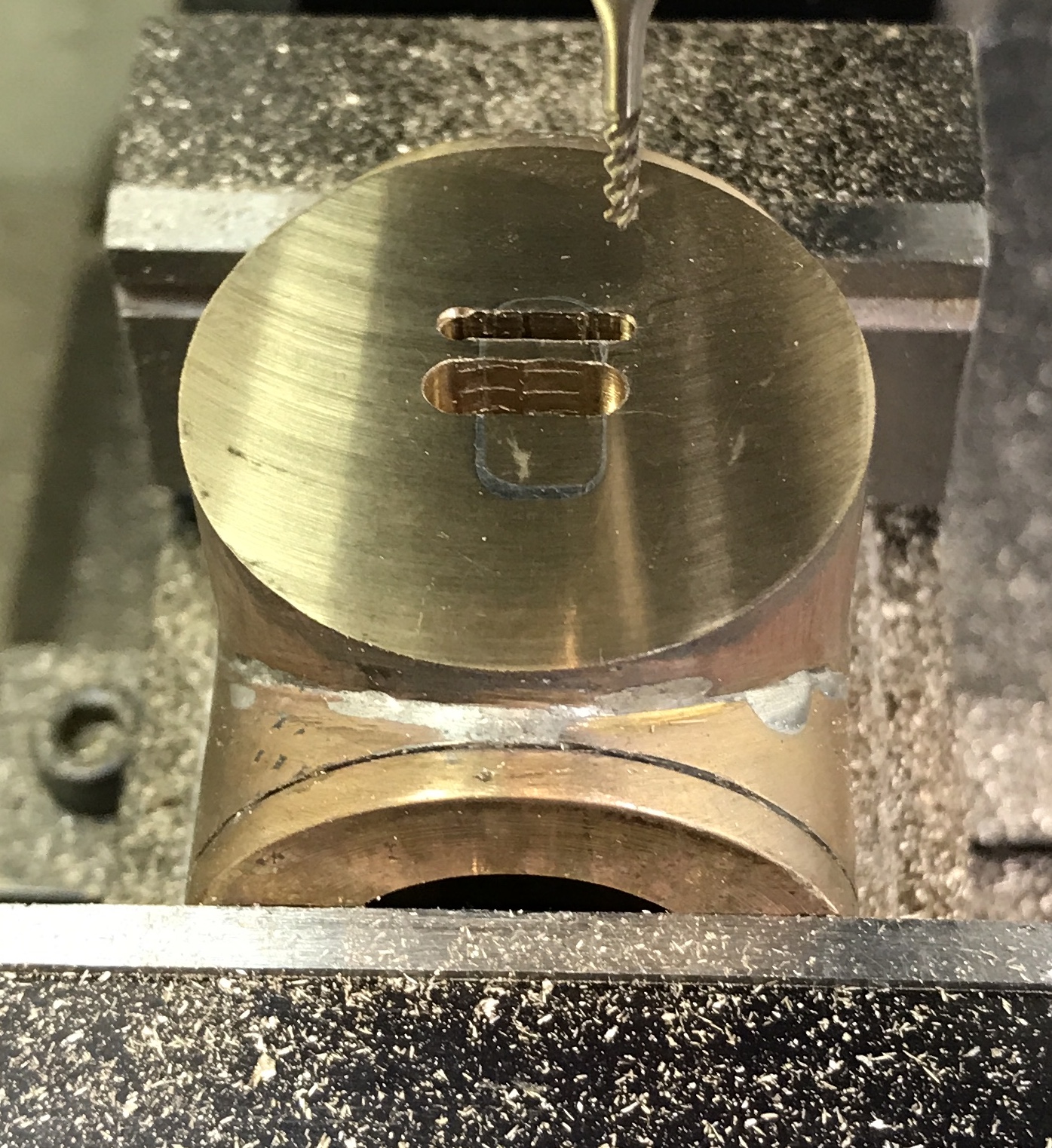
The cylinder was reoriented in the vise for better clamping. The face was releveled. The center of the face was located. (Remember the cylinder is 1.280" in diameter!) A pilot hole was drilled with a center drill. The holes on either side were then drilled with the center drill as well. (0.125" between hole centers) The three holes were drilled 0.30" deep with a 1/8" drill leaving a slim web between them. The depth was determined by adjusting the spindle until the drill tip just touched a ruler lying on the face. The ruler was measured at 0.044". The first photo below shows the three drilled holes. The drill was switched for a 1/8" end mill. The slot was milled in 0.030" increments back and forth with frequent chip removal using canned air. The slot was milled to a depth of 0.310". The second photo shows the milled slot.
The center of the steam port slots are 5/32" (0.156") above and below the center of the exhaust port slot. This leaves 1/16" between the walls of the slots. The center of the 1/16" drill also needs to be 1/32" from the spindle location for the 1/8" end mill when it is positioned at the end of the exhaust port slot. Six 1/16" holes will fill the 3/8" slot. Slot depth for the steam port slots is the same 0.31".
The spindle was moved as described above. Six holes were center drilled. Only three holes were drilled with the 1/16" drill as the drill attempted to jump back to the first hole from the second. The drill was switched to a 1/16" end mill held in a 3/16" collet. The slot was milled in 0.020" increments. The end mill was moved very slowly and the slot was cleared of debris after every pass. The cutting part of the end mill is only 0.280" long so I had the force the last 0.020" and stopped at 0.300" deep. A deeper chamfer from the center drill should allow the second slot to be milled to 0.31". The photo shows the nice result.
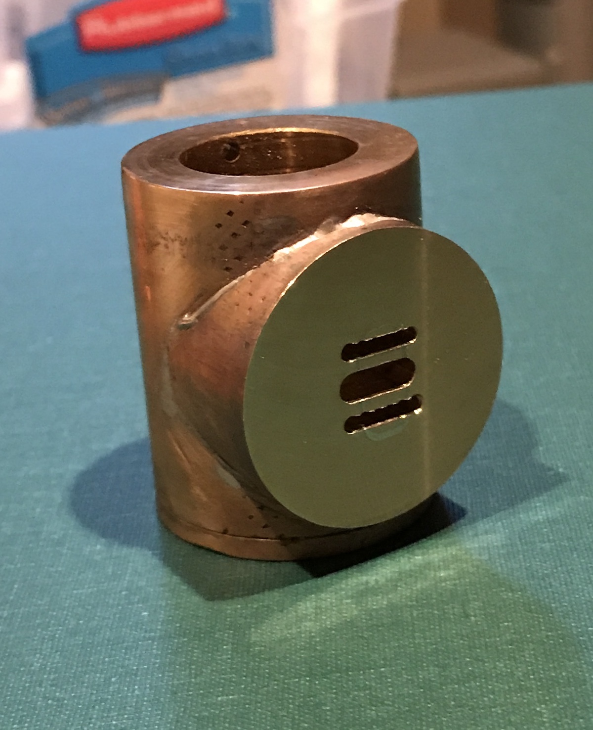
The second steam port slot was made similarly, with only a few changes. The chamfer was made a little bigger. A #54 drill (0.055") was used to drill all six holes. The milling was done as above, but to a depth of 0.310". The photo below shows all three completed slots.
One hole needs to be drilled in from the side of the cylinder to meet the exhaust slot. This exhaust passage was drilled with a #21 drill and tapped 10-32 for a depth of 0.19". This hole is centered 0.250" from the face.
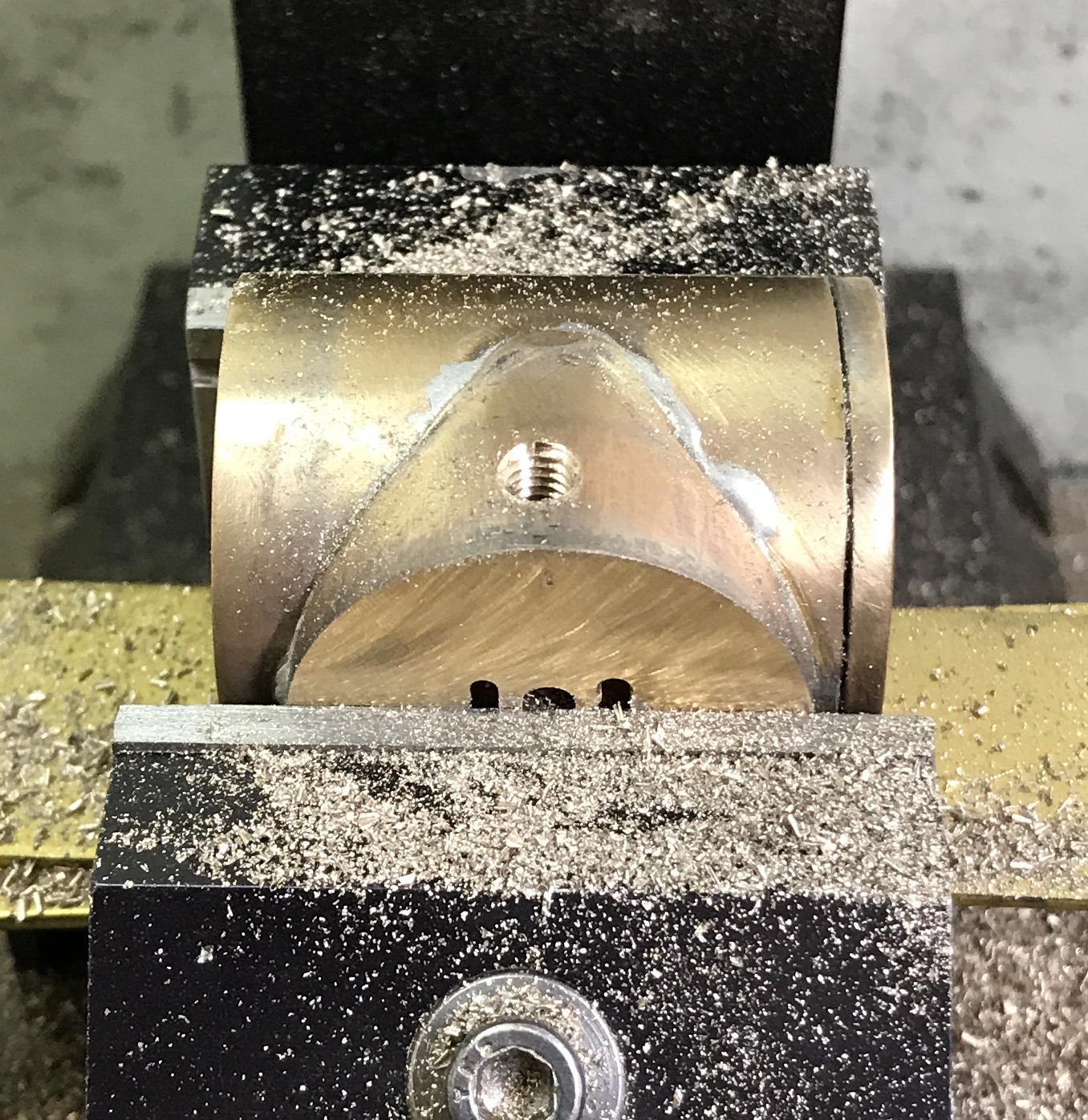
The next step is drilling four holes in from each end to reach the steam slots. Four holes span the 0.375" putting them on 0.094" centers. A #47 drill (0.078") is used to drill the four holes. The first challenge is locating their positions. The side of the face was located and the spindle moved in 0.64". The face was located and the spindle moved in 0.28". The spindle was moved a further 0.149" sideways. The first hole was drilled until the slot was hit. The spindle was moved 0.094" back toward center and the second hole was drilled. The was repeated two more times. A 3/16" end mill was used to cut the 1/8" deep pocket into the just drilled holes. The result of these operations is seen below.